
D
Donald HolmesAug 14, 2025
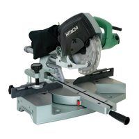
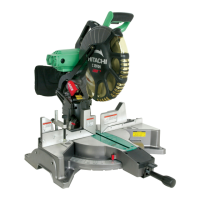
What to do if Hitachi Saw blade is locked?
- LlisacampbellAug 14, 2025
If your Hitachi Saw blade is locked, it could be due to several reasons: * The cutting speed might be too fast, so try reducing it. * The core diameter of your extension cord might be too small; use a thicker and shorter one. * A dull saw blade can cause excessive cutting force, so resharpen it. * Using an incorrect saw blade can also be the issue. Use a suitable Hitachi-supplied saw blade. Remember, a saw blade with more teeth increases cutting resistance, so reduce the cutting speed when using one. * The workpiece might be warped or bent, causing the saw blade to bind. Correct this with a planer.