MODELS CR 12V/CR 12
− 1 −
1. NOTES ON DISASSEMBLY AND REASSEMBLY:
The circled numbers in the descriptions below correspond to the item numbers in the Parts Lists and ex-
ploded assembly diagrams.
1-1. Diassembly:
(1) Disassembly of the Upper Cover Ass’y
11
:
After removing the Base
1
and the Saw Blade
501
, take off the Insulation Cover
2
by pulling it
forward (toward the blade mounting end). Then, shift the Plunger
5
forward (toward the blade
mounting end) and loosen the four M5 x 16 Machine Screws
10
which secure the Upper Cover Ass’y
11
. The Upper Cover A’ssy can then be removed by lifting it upwards.
(2) Disassembly of the Plunger
5
from the Upper Cover Ass’y
11
:
First remove the two M5 x 12 Hexagon Socket Flat Hd. Screws
15
which secure the Connector
14
.
As these are seal lock screws which are secured by an adhesive agent, it may be necessary to heat the
Upper Cover Ass’y
11
to a temperature of 100°C - 150°C to permit their removal. The Plunger
5
can then be removed from the Upper Cover Ass’y
11
by pulling it out toward the front (toward
the blade mounting end) .
(3) Disassembly of the Gear Cover
26
from the Housing Ass’y
42
:
Remove the Brush Caps
39
, and take out the Carbon Brushes
40
. Next, remove the four D5 x 35
Tapping Screws
45
. The Gear Cover
26
(together with the Armature
30
and ralated parts) can then
be removed from the Housing Ass’y
42
.
(4) Disassembly of the Armature
30
from the Gear Cover
26
:
Remove the three M4 x 12 Machine Screws
44
. The Armature
30
(together with the Bearing Cover
29
) can the be removed from the Gear Cover
26
.
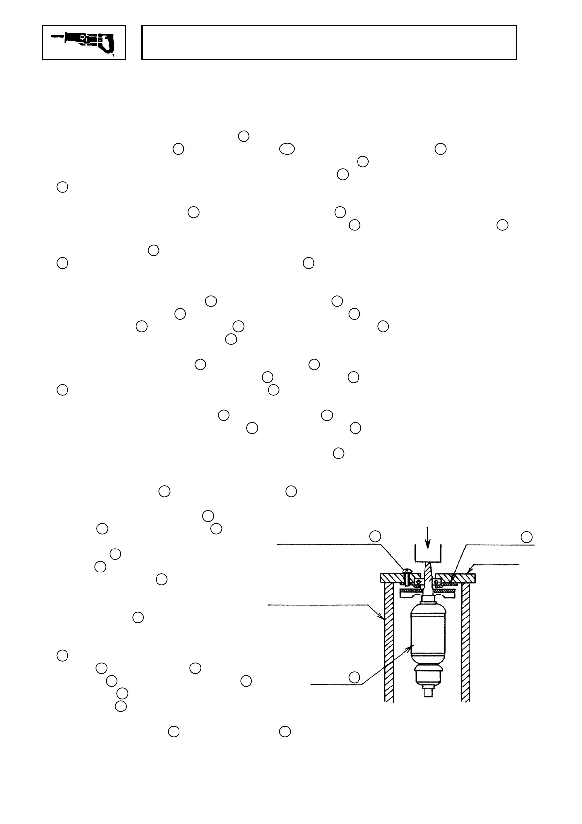
(5) Disassembly of the Bearing Cover
29
from the Armature
30
:
First, remove the C-Type Retaining Ring
27
from the Armature
30
. Then, as illustrated in Fig.5,
mount the Armature on a J-173 Puller Attachment (special repair tool, Code No. 970954) , and
secure it in position with the three M4 x 12 Machine Screws
44
. Next, support the J-173 Puller
Attachment with an appropriate tubular jig (inner diameter of 80 mm or more, outer diameter of
130 mm of less) , and push down on the Pinion end of the Armature with a hand press to loosen and
remove the Armature
30
from the Bearing Cover
29
.
(6) Disassembly of the Gear Ass’y
21
and
Spindle
25
from the Gear Cover
26
:
Remove the M6 x 16 Hexagon Socket Flat
Hd. Screw
18
which secures the Balance
Weight
19
, and remove the Balance Weight
from the Gear Cover
26
. As this screw
is a seal lock screw which is secured by an
adhesive agent, it may be necessary to heat
the Gear Cover
26
to a temperature of
100°C - 150°C to permit its removal. Then,
through the hole provided in the Gear Ass’y
21
, remove the three M4 x 12 Flat Hd.
Screws
22
. The Gear Ass’y
21
, Bearing
Cover (A)
23
, 6202VVCM Ball Bearing
24
and Spindle
25
can be taken out of the
Gear Cover
26
in a single body. Finally,
push down on the gear-side end of the Spindle
to separate the Spindle
25
from the Gear Ass’y
21
. .
J-173 Puller
Attachment
Tubular Jig
Inner Dia: 80mm or more
Outer Dia: 130mm or less
M4 x 12 Machine Screws
44
(3 pcs)
Armature
30
Bearing Cover
29
Push
Fig. 5
 Loading...