-20-
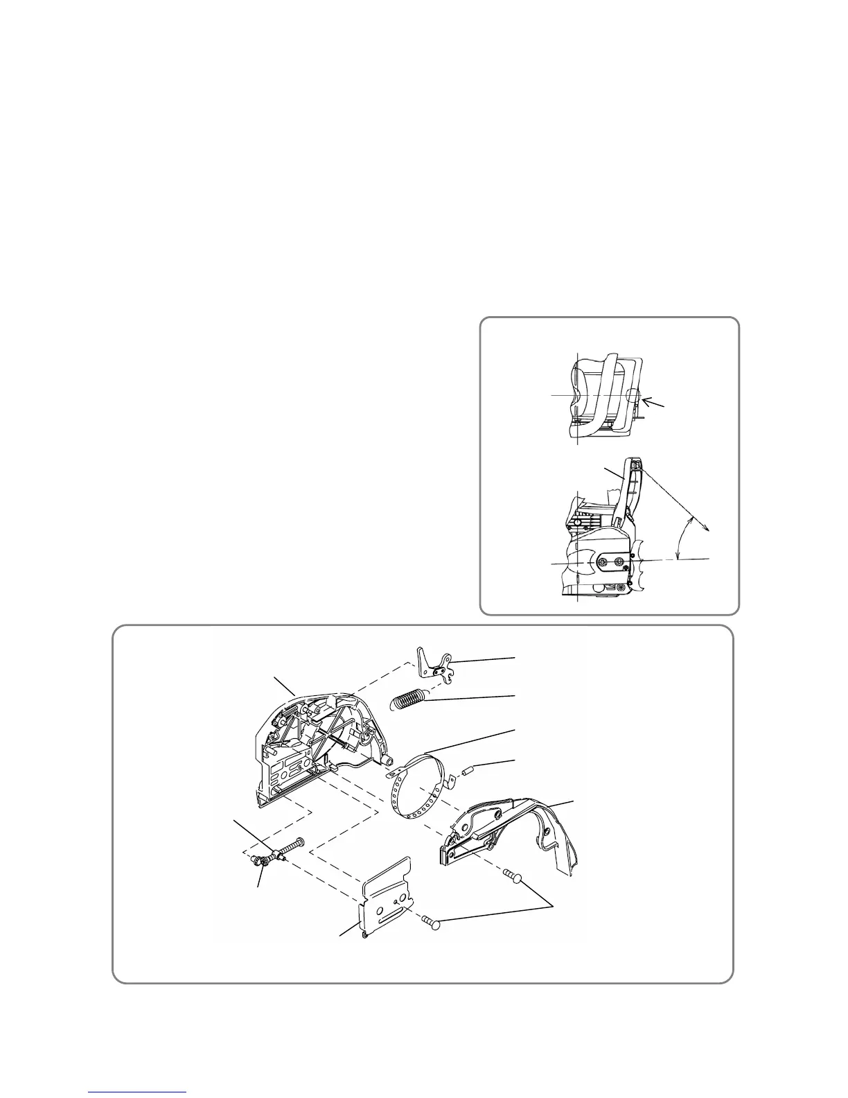
Ɣ Operation check of the chain brake
Loading
direction
Loading position
Brake Handle [89]
40 to 50°
Ɣ Side case
Brake Link [126]
Brake Spring [127]
Brake Band [128]
Needle Roller D3 [129]
Brake Link Cover [130]
Chain Puller Bolt [114]
Guide Plate (B) [116]
Side Case Sub [113]
Seal Lock Screw M4 x 10 [16]
Chain puller boss
13. Disassembly and reassembly of the side case
[Tool required]
Ɣ Phillips screwdriver
(1) Disassembly
Ɣ Remove Flange Nut M8 [112] and remove the side case from the main body.
Ɣ With the Brake Link [126] being held in a vise, push it down to apply the brake.
Ɣ Use a Phillips screwdriver to remove the six Seal Lock Screws M4 x 10 [16]. Then remove the
components of the side case, such as Brake Band [128].
CAUTION: The threads of the Seal Lock Screws M4 x 10 [16] may be easily broken. Therefore,
do not tighten the screws too much.
(2) Reassembly
Reassembly can be conducted by reversing the disassembly procedure. However, special attention
should be given to the following items.
Ɣ Do not reuse the Seal Lock Screws M4 x 10 [16].
Ɣ Align Guide Plate (
B) [116] with the groove of the
Brake Link Cover [130] when mounting.
Ɣ After mounting, use a vise to hold the Brake Link
[126], and then push it up until you hear a click to
release the brake.
Ɣ Operate the Chain Puller Bolt
[114] and confirm
that the
chain puller boss moves.
Ɣ After reassembly, operate the Brake Handle [89] to
confirm chain brake activation. The chain brake
must operate at F = 20 N to 60 N (2.04 kgf to 6.12
kgf). (See the drawing on the right.) Upon ensuring
activation, release the chain brake.
 Loading...