--- 16 ---
(6) Disassembly of the clutch unit
(a) After pressing up the hook of Front Case [9] <9> with the small flat-blade screwdriver, the Clutch Dial [4]
<4> and the Click Spring [5] <5> can be taken out as they are. (See Fig. 2.)
(b) Turn the Nut [6] <6> counterclockwise and remove it from the Front Case [9] <9>, then remove the Spring
[7] <7> and Washer (D) [8] <8> from the Front Case [9] <9>.
NOTE: Do not remove the Front Case [9] <9>.
(7) Disassembly of the power supply unit
NOTE: Do not remove the heat sink secured to the DC-Speed Control Switch [32] <33> with a screw.
Remove the two Machine Screws (W/Sp. Washer) M4 x 6 [28] <29>, and take the Motor [25] <25> and the
Motor Spacer [24] <24> apart. Disconnect the Internal Wires [30] [31] <31> <32> from the Motor [25] <25>
with a soldering iron, then disconnect them from the DC-Speed Control Switch [32] <33> with a soldering iron
in the same manner.
Fig. 1
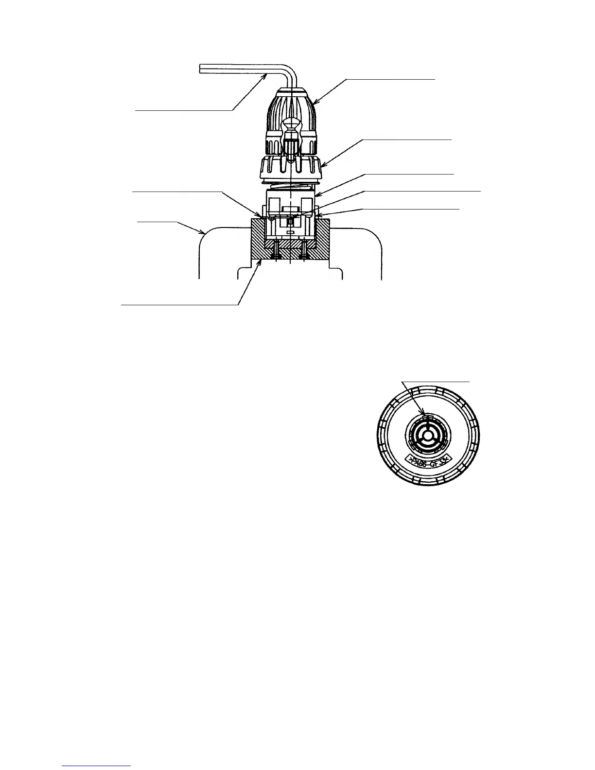
(5) Disassembly of the gear unit
Remove the Shift Arm [16] <16> from the Rear Case [14] <14>,
then remove the Screw Set D3 x 12 (4 pcs.) [15] <15>
connecting the Front Case [9] <9> and the Rear Case [14] <14>.
Remove Washer (A) [13] <13>, Planet Gear (C) Set (3 pcs.) [12]
<12>, Ring Gear [11] <11>, six Steel Balls D5 [10] <10> from the
Front Case [9] <9> in order. Take care not to lose the six Steel
Balls D5 [10] <10> in this operation.
Fig. 2
Hook (3 pcs.)
Drill Chuck [2] <2>
Clutch Dial [4] <4>
Front Case [9] <9>
Slide Ring Gear [17] <17>
Rear Case [14] <14>
Hexagonal bar wrench
Shift Arm [16] <16>
Vise
Special repair tool (J-342)
 Loading...