−#2 −
(3) After Housing (B) has been removed, the parts inside may either be removed together in an assembled
state, or removed individually. First, remove the Shift Arm-Shift Knob Set
17
, being very careful not to allow
the Shift Spring
18
to fly out unexpectedly.
(4) Removal of the Motor
21
:
(a) Take off the Cap
9
, Spring Holder
10
, Spring
11
, Thrust Plate
12
, and Steel Balls
14
, in that order. At
this time, be particularly careful not to lose the four Steel Balls
14
.
(b) Remove the four D3 x 8 Tapping Screws
16
, and remove the Motor
21
.
(5) Disassembly of Electrical Components:
[NOTE] The three lead wires from the FET (Field Effect Transistor) and the two lead wires from the Diode
are permanently connected to the Switch Ass’y
22
and should not be detached.
Remove the single M3.5 x 8 Bind Screw
26
. The FET of the Switch Ass’y
22
and the Fin can then be
disassembled. Remove the single M3 x 10 Bind Screw
25
. Then, use a soldering iron to disconnect the
lead wires of the Switch Ass’y
22
from the Motor
21
and the lead wires of the Switch Ass’y
22
from the
Terminal
28
.
1-1-2. Reassembly:
Reassembly can be accomplished by following the disassembly procedure in reverse. However, special
attention should be given to the following points.
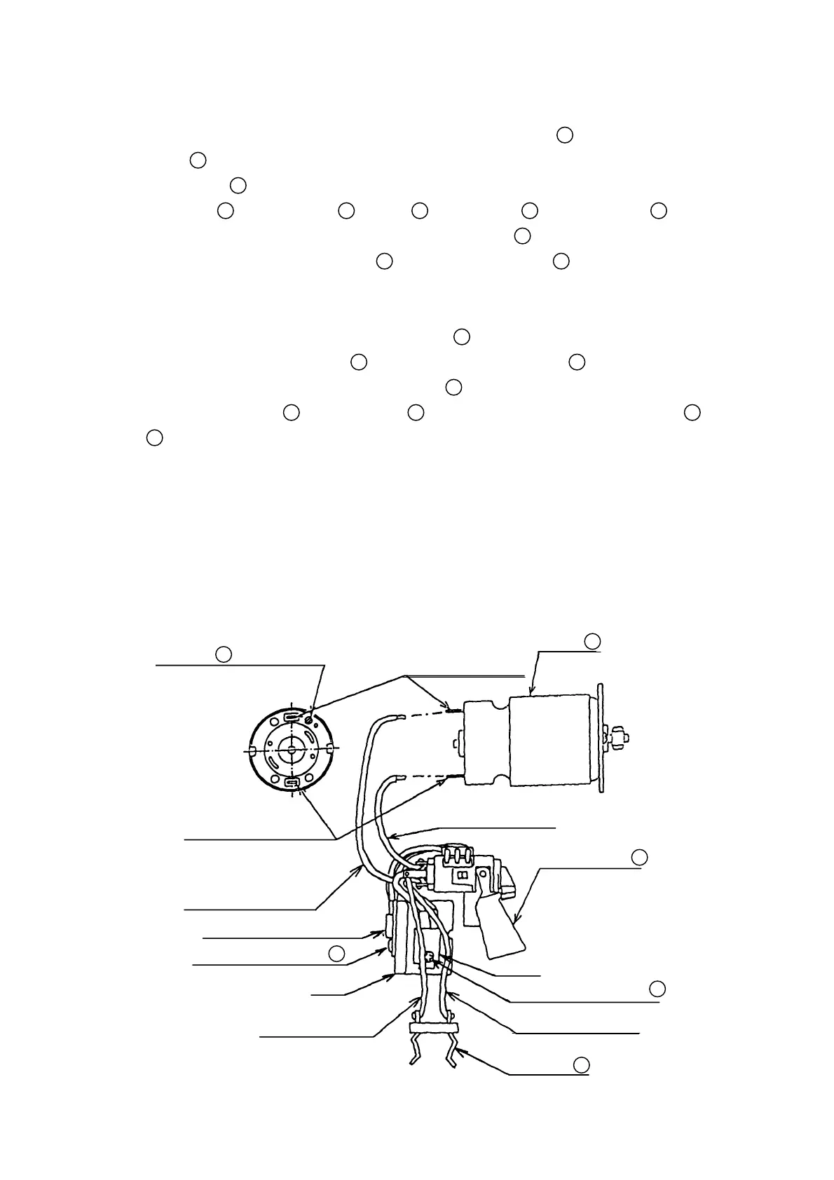
(1) Reassembly of Electrical Components:
(a) Ensure that the wiring is connected as shown in the diagram in Fig. 2.
The red mark indicates the
positive (
+
) terminal side.
Negative Terminal
Negative Terminal
Lead wire (Yellow)
M3.5 x 8 Bind Screw
26
Fin
Lead wire (White)
Positive Terminal
Motor
21
Lead wire (White)
Switch Ass’y
22
Diode
M3 x 10 Bind Screw
25
Lead wire (Yellow)
Terminal
28
Fig. 2