−#3 −
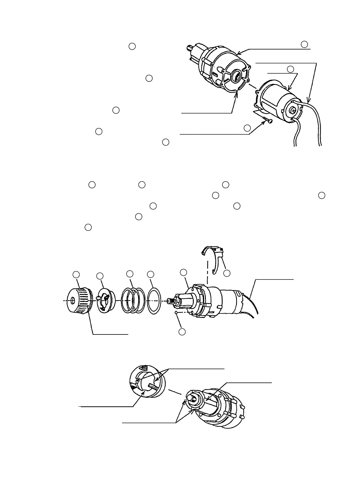
(2) Connecting the Spindle Gear Set
13
and the
Electrical Components Assembled as Described
in Para. (1):
When connecting the Spindle Gear Set
13
and the
electrical components assembled as described in
Para. (1) above,ensure that the colored lead
wires soldered to the Motor
21
are correctly
positioned with relation to the notched portion of
the Spindle Gear Set
13
before fastening the two
sections with the four D3 x 8 Tapping Screws
16
.
(See Fig. 3)
(3) Reassembly of the Clutch Section:
Assemble the Cap
9
and Shift Arm
15
onto the Spindle Gear Set
13
. (See Fig. 4)
During assembly,be very careful not to allow the four Steel Balls
14
to drop out of the Spindle Gear Set
13
.
(a) When assembling the Spindle Holder
12
onto the Spindle Gear Set
13
, ensure that the notched
portions of the Spindle Gear Set
13
are properly aligned with the matching protruding portions of the
Spring Holder
12
. (See Fig. 5)
Fig. 4
Fig. 5
Protruding Portions
Notched Portion
Protruding Portion
Notched Portion
Internal Wire
(Yellow)
White Line
9
10
11
12
13
14
15
Spindle Gear Set
13
Internal Wire (Yellow)
Motor
21
Tapping Screw D3 x 8
16
Notched Portion
Fig. 3