−#4 −
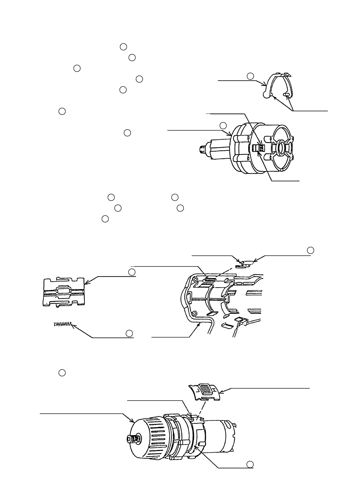
(b) When assembling the Cap
9
onto the components assembled as described in Para. (a) above, ensure
that the white line on the Cap
9
is properly aligned with relation to the colored lead wires soldered to
the Motor
21
. (See Fig. 4)
(c) When assembling the Shift Arm
15
onto the Spindle Gear Set
13
, ensure
that the protruding portions of the Shift
Arm
15
are properly fitted into the
matching grooves of the ring gear
inside the Spindle Gear Set
13
. (See
Fig. 6)
Fig. 6
(d) Insert the Shift Spring
18
into the Shift Knob
17
. (See Fig. 7)
(e) Assemble Bit Holder (A)
19
and Bit Holder (B)
5
respectively into Housing (A) and Housing (B) of the
Housing (A) (B) Set
3
. At this time, ensure that the insert portions of the Bit Holders are properly
installed into the insert receiving sockets of the Housings. (See Fig. 8)
Fig. 7 Fig. 8
(f) Mount the components assembled as described in Para. (d) onto the protruding portions of the Shift
Arm
15
that is mounted on the components assembled as described in Para. (a). (See Fig. 9)
Parts assembled in Para. (a)
Parts assembled in Para. (d)
Protruding Portion
Shift Arm
15
Fig.9
Protruding
Portions
Shift Arm
15
Ring Gear
Spindle Gear Set
13
Grooves
Shift Knob
17
Insert Portion
Shift Spring
18
Bit Holder (A)
19
Insert Receiving Pocket
Housing (A)