Do you have a question about the Hitachi FSXN1E Series and is the answer not in the manual?
Information about publication reproduction, copyright, and continuous product improvement policies.
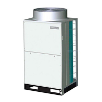
Guide to product models, including classification and special models.
Instructions for checking model name, system type, and codes before installation.
Details on the classification of outdoor unit models based on type, capacity, and features.
Information on special models for high performance installations, referencing technical catalogue data.
Details on combining FSXN1E outdoor units to achieve different capacities from 8 to 54HP.
Details on combining FSXNH outdoor units for capacities from 5 to 36HP.
Provides critical safety information regarding electrical hazards, installation precautions, and system operation.
Explanation of symbols used in the manual to indicate hazards and important information.
Provides critical safety information regarding electrical hazards, installation precautions, and system operation.
Details on the high pressure vessel and safety device within the air conditioning unit, including warnings.
Outlines the manual's purpose and the importance of adhering to installation and safety instructions.
Specifies the operating temperature ranges for cooling and heating modes for the system.
Details the automatic functions of the system, including compressor protection and defrost cycles.
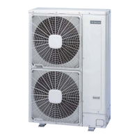
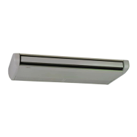
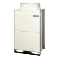
Identifies and lists the various parts of the RAS-8FSXN1E outdoor unit with corresponding numbers.
Identifies and lists the various parts of the RAS-(10/12)FSXN1E outdoor unit with corresponding numbers.
Identifies and lists the various parts of the RAS-(14/16)FSXN1E outdoor unit with corresponding numbers.
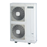
Identifies and lists the various parts of the RAS-(5/6)FSXNH(E) outdoor unit with corresponding numbers.
Identifies and lists the various parts of the RAS-(8-12)FSXNH(E) outdoor unit with corresponding numbers.
Diagram and list of components for the refrigerant cycle of RAS-(8-12)FSXN1E outdoor units.
Diagram and list of components for the refrigerant cycle of RAS-(14/16)FSXN1E outdoor units.
Diagram and list of components for the refrigerant cycle of RAS-(5/6)FSXNH(E) outdoor units.
Diagram and list of components for the refrigerant cycle of RAS-(8-12)FSXNH(E) outdoor units.
Instructions for secure transport of outdoor units, including fastening methods and storage precautions.
Guidelines for safely handling units with fork-lift trucks, emphasizing prevention of injury and damage.
Detailed method for lifting units, specifying the use of slings and avoiding metal cables.
Provides center of gravity data for various outdoor unit models to aid in lifting and handling.
Specifies conditions for outdoor unit placement, considering sunlight, ventilation, noise, and access.
Defines the required installation space around outdoor units based on wall configurations and ventilation needs.
Provides guidance on installation procedures, considering wall configurations and environmental factors.
Provides installation space requirements for units adjacent to buildings with walls in two directions.
Details installation space requirements for units installed with walls in three directions.
Specifies installation space requirements for units installed with walls in all four directions.
Discusses factors affecting installation space, such as outdoor temperature and airflow, for optimal system performance.
Details requirements for foundations and anchoring outdoor units, ensuring stability and proper drainage.
Specifies requirements for outdoor unit foundations, including height, drainage, and strength considerations.
Details the correct positioning of anchorage bolts for securing the outdoor unit to its foundation.
Guidelines for selecting refrigerant pipe sizes based on system type and outdoor unit power, with warnings on incorrect sizes.
Guidelines for selecting refrigerant pipe sizes based on system type and outdoor unit power, with warnings on incorrect sizes.
Information on copper pipe specifications, sizes, connection methods, and insulation requirements for refrigeration systems.
Details on how to perform pipe flaring operations and requirements for flare fitting connections.
Specifications and diagrams for various pipe connection kits used with SET FREE FSXN1E series systems.
Details pipe sizes for SET FREE FSXN1E series (3 pipes) for different combinations of outdoor and indoor units.
Provides crucial precautions for installing outdoor units, including order of units and pipe installation between them.
Specifies pipe sizes for 2-unit combinations of FSXN1E and FSXNH(E) outdoor units.
Specifies pipe sizes for 3-unit combinations of FSXN1E and FSXNH(E) outdoor units.
Specifies pipe sizes for 4-unit combinations of FSXN1E outdoor units.
Provides general guidelines for installing refrigerant pipes, including flared connections and insulation.
Instructions and torque values for mounting flared pipe connections in refrigeration systems.
Guidelines for insulating refrigerant pipes to prevent temperature loss, energy loss, and condensation.
Details piping connections for heat pump and heat recovery systems, including diagrams and size specifications.
Details piping connections for heat pump systems (2 pipes), including diagrams and size specifications.
Details piping connections for heat recovery systems (3 pipes), including diagrams and size specifications.
Restrictions and guidelines for branching refrigerant pipes, especially for longer runs and combinations.
Specifics on pipe branching for 2-pipe and 3-pipe systems, including length and size considerations.
Example illustrating pipe length and size adjustments for piping from a multikit to indoor units within 40-90m.
Tables detailing pipe diameters for various system configurations and unit combinations.
Table detailing pipe diameters for heat pump systems (2 pipes) based on HP and equivalent pipe length.
Table detailing pipe diameters for heat recovery systems (3 pipes) based on HP and unit combinations.
Details pipe diameters for outdoor units and connections in heat recovery systems (3 pipes).
Specifies pipe diameters after the first branch for heat recovery systems (3 pipes) based on total HP indoor unit capacity.
Procedure for ensuring the refrigerant piping system is airtight, including valve checks and pressure testing.
Details the correct torque for tightening stop valve spindles and flare nuts during air-tight testing.
Provides cautions regarding stop valve operation, particularly in cold conditions and avoiding excessive force.
Describes the method for performing an air-tight test using nitrogen gas, vacuum pumps, and leak detectors.
Instructions for securely insulating refrigerant pipes and piping covers to prevent damage and condensation.
Procedure for vacuum pumping the refrigerant system to remove moisture and air, ensuring proper pressure levels.
Method for calculating the required additional refrigerant charge based on piping length, unit capacity, and system configuration.
Details the calculation steps for determining additional refrigerant charge (W1, W2, W3, W4) for the system.
Table showing the maximum allowable additional refrigerant charge quantity based on outdoor unit HP.
Instructions for charging the system with R410A refrigerant and recording the total charge.
Guidance on recording the total refrigerant charge after additional charging for maintenance purposes.
Specific calculation method for additional refrigerant for wall type units with expansion valve kits.
Step-by-step instructions for charging the system with additional refrigerant, including valve operations and safety checks.
Provides crucial cautions when opening stop valves, particularly regarding pressure and potential refrigerant leakage.
Explains the automatic system for judging the refrigerant amount and troubleshooting abnormal results.
Step-by-step guide to perform the refrigerant amount check operation using the automatic judgement system.
Details the results indicated by the 7-segment display and the corresponding actions for sufficient, excessive, or insufficient refrigerant.
Highlights critical gas concentration limits and necessary measures to prevent accidental refrigerant gas leakage.
Emphasizes safety precautions and regulatory compliance in the event of refrigerant leaks.
Specifies the maximum permitted concentration of HFC gas (R410A) in air to prevent suffocation.
Method for calculating refrigerant concentration in a room based on total refrigerant quantity and room volume.
Lists characteristics for rooms to mitigate risks in case of refrigerant leaks, including ventilation and fans.
Details the condensation drainage system requirements for outdoor units, including location and drainage kit usage.
Details the condensation drainage system requirements for outdoor units, including location and drainage kit usage.
General precautions and safety guidelines for electrical wiring work on indoor and outdoor units.
Checks to ensure correct electrical components, voltage supply, and wiring connections are made according to regulations.
Illustrates power source wiring diagrams for heat pump and heat recovery systems, detailing component connections.
Wiring diagram for connecting power sources to outdoor and indoor units in a heat pump system.
Wiring diagram for connecting power sources to outdoor and indoor units in a heat recovery system.
Specifies minimum wire sizes for power source and transmission cables based on unit model and power supply.
Details electrical data and recommended wiring, including breaker sizes for each outdoor unit.
Provides specifications for service voltage, start-up voltage, voltage imbalance, and electromagnetic compatibility.
Information on harmonic compliance with IEC standards, including short circuit current requirements.
Instructions for connecting electrical wiring to the outdoor unit's terminal board and PCB.
Details how to connect indoor units, CH units, and communication cables to the outdoor unit.
Explains the location and setting of DSW switches on the PCB1 for various system configurations and modes.
Diagram showing the physical location of DSW and PSW switches on the PCB1.
Instructions for setting the refrigerant cycle number using DSW1 and RSW1 switches.
Guidance on setting the capacity using DSW2 switches, including requirements for different unit combinations.
Instructions for setting the outdoor unit number using DSW6 switches, distinguishing between base and combination units.
Details on setting the supply voltage using DSW7 switches.
Instructions for communication settings using DSW10 switches, including H-LINK and H-LINK II configurations.
Explanation of DSW4 settings for test run, service operations, and compressor stoppage.
Details DSW5 settings for emergency operation, test run, and service, including refrigerant quantity monitoring.
Configuration options for external inputs, outputs, and specific system functions through the PCB.
Essential checks to perform before executing the test run, including refrigerant pipes, wiring, and unit settings.
Procedure for performing the test run on indoor units and verifying system conformity and operation.
Instructions for initiating and performing a test run using the PC-ART remote controller.
Guide for executing the test run procedure using the PC-ARF remote controller.
A checklist for verifying all critical parameters and operations during the test run.
| Brand | Hitachi |
|---|---|
| Model | FSXN1E Series |
| Category | Air Conditioner |
| Language | English |