R
Ryan JonesAug 3, 2025
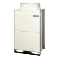
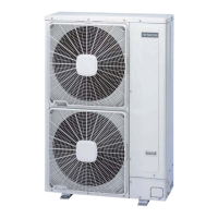
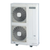
How to check if the power source breaker or the fuse is blown on a Hitachi FSXN?
- JJennifer McmillanAug 3, 2025
To check if the power source breaker or fuse is blown on your Hitachi Air Conditioner, examine the voltage on the secondary side of the breaker. Then, use a multimeter to check the continuity of the fuse.