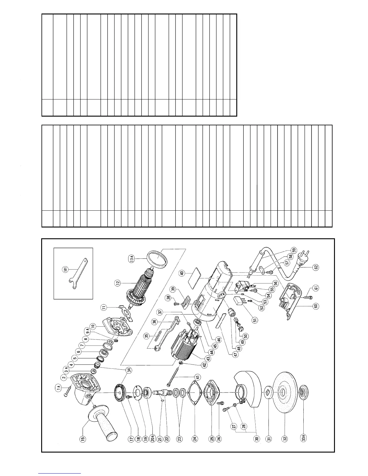
G12SA The exploded assembly drawing should be used only for autorized service center.
Item
No.
Part Name
41 Tapping Screw
(W/Sp. Washer) D4 x 75
42 Earth Washer D4
43 Stator Ass’y
44 Bearing Lock
45 Ball Bearing
(608VVMC2EPS2L)
46 Housing Ass’y
47 HITACHI Label
48 Brush Holder
49 Carbon Brush
50 Brush Cap
51 Noise Suppressor
52 Terminal
53 Hex. Socket Set Screw M4 × 5
54 Tapping Screw (W/Washer)
D4 × 12
55 Slide Switch
56 Tube (D)
57 Tapping Screw (W/Washer)
D4 × 16
58 Cord Clip
59 Cord Armor
60 Tail Cover
61 Tapping Screw D4 × 25
62 Cord
501 Wrench
Parts are subject to possible
modification without notice due to
improvements. The drawing and the list
are parts structural drawing and parts
list of model G12SA. For model G13SB
refer to the drawing and the list.
Item
No.
Part Name
1A Tapping Screw D5 × 30
2 Gear Cover
3A Seal Lock U-Nut M8
4 Pinion
5 Seal Ring (A)
6 Ball Bearing
(629DDMC3EAV2S)
7 Rubber Ring
8 Felt
9A Spring
10 Inner Cover
11 Lock Plate
12 Armature
13A Fan Guide
15 Side Handle
17 Gear
18 Seal Lock Screw
(W/Sp. Washer) M4 × 10
19 Bearing Cover (B)
20A Ball Bearing
(6201DDUCMAV2S)
21 Feather Key 3 × 3 × 8
22 Spindle (A)
23 Felt Packing D18
24 Seal Packing
25 Packing Gland
26 Seal Lock Screw
(W/Sp. Washer) M5 × 16
27 Machine Screw M50 × 20
28 Spring Washer M5
30 Wheel Guard (A) Ass’y
31 Wheel Washer
32 D. C. Wheels 115MM A36Q
33A Wheel Nut
34 Gear Ass’y
35 Spring
36 Slide Bar
37 Brush Terminal
38 Flat Hd. Screw M4 × 10
39 Slide knob (C)
40 Name Plate