GS4000 Installation Guide Revision 4.00
520-10-026-30X
1-37
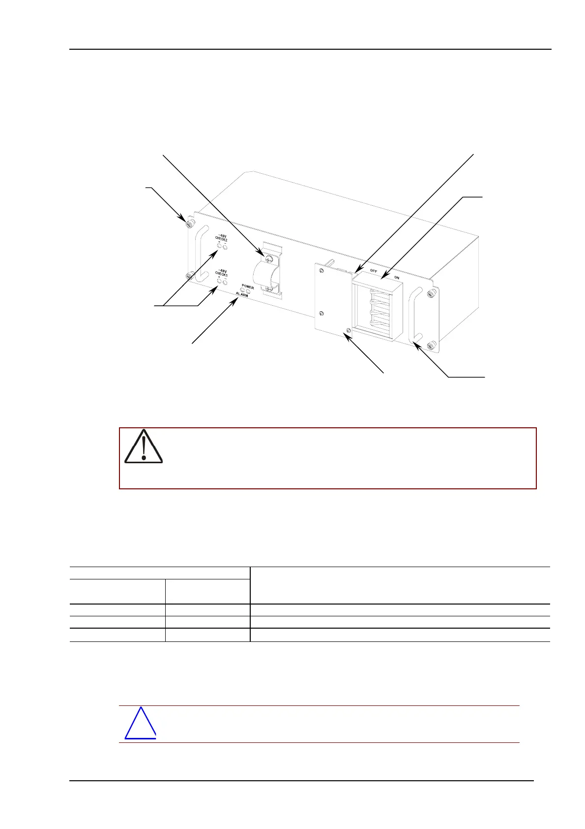
1.3.4 POW-MSDCE
This is the DC-48/60V power supply used for GS4000-160E2 and GS4000-320E.
(1) Outer Appearance
As for the LED, see Table 1.3-4.
Figure 1.3-4 Outer Appearance of POW-MSDCE
WARNING: TO MEASURE THE VOLTAGE AT A DC-POWERED DEVICE, THE END
TERMINAL IS ATTACHED TO POW-MSDCE. ONLY TRAINED ENGINEERS OR
MAINTENANCE SERVICE PERSONELL ARE ALLOWED TO MEASURE THE
VOLTAGE. TO AVOID A FIRE OR AN ELECTRIC SHOCK, DO NOT INSERT
SMALL PINS OR PAPER CLIPS INTO THE TERMINAL.
(2) LEDs
In the DC-48/60V power supply for GS4000-160E2 and GS4000-320E2, the action status is
indicated by the combination of the two LEDs as shown in Table 1.3-4.
Table 1.3-4 LED Indicators on the POW-MSDCE Front Panel
Name
POWER
(LED: Green)
ALARM
(LED: Red)
Action Status
Power ON Power OFF Output voltage is normal.
Power OFF Power ON Output voltage is abnormal.
Power OFF Power OFF
Power is OFF or the output voltage is abnormal.(Note)
Note: There is the possibility that both POWER LED and ALARM LED are powered off depending on the contents of a
trouble.
(3) Accessories
No accessories provided.
*
NOTE: DC cables must be prepared by the customers themselves.
LEDs
Circuit
Breaker
Mounting
Screw
Terminal
Board
Cable Clamp
Handle
Terminal
Board Cover
Potential Tap
(Read the
Warning below.)
 Loading...