-26-
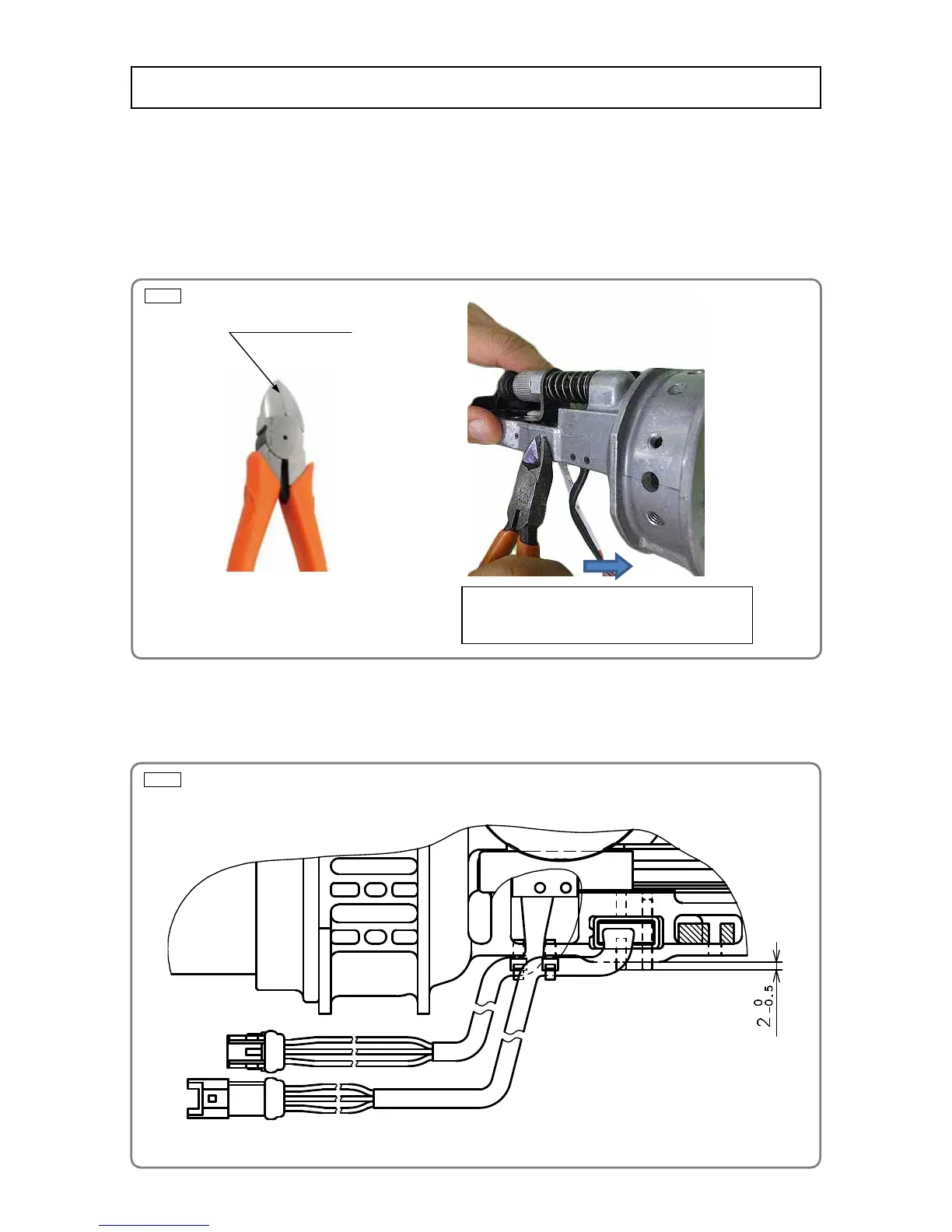
Fig. 32
Fig. 33
• Remove Housing (C) [45](45), magazine ass'y, and Top Cover [2](2) to take out the power assembly
referring to pages 8 to 12.
• Remove the Nylock Hex. Socket Hd. Bolt M3 [69](69) and Guide Plate Holder [65](65) from the Nose
[17](17), then remove Guide Plate (P) [68](68).
• Pull out the Roll Pin D2.5 [66](66) and Roll Pin D2.5 x 16 [67](67) protruding from the Nose [17](17) with
nippers as shown in Fig. 32.
• Remove Sensor (B) [63](63) from the Nose [17](17).
• Mount new Sensor (B) [63](63) to the Nose [17](17) and then mount the Roll Pin D2.5 [66](66) as shown
in Fig. 33.
A
Hold the roll pin with the blade edges of nippers.
Pressing against the end surface of the nose, move
the nippers in "A" direction to pull out the roll pin.
Use nippers having no
dent at the blade edges.
Replacement of sensor (B)
 Loading...