4
(2) As shown in Fig. 5, remove the carbide blade by
sliding it with the attached box wrench.
Fig. 5
CAUTION
䡬 Be careful not to injure your hands.
2. Carbide blade assembly:
CAUTION
䡬 Prior to assembly, thoroughly wipe off all swarf
accumulated on the carbide blade.
(1) As shown in Fig. 6, lift set plate (B) and insert the new
carbide blade between cutter block and set plate (B).
Fig. 6
(2) As shown in Fig. 7, mount the new carbide blade by
sliding it on the set plate (B) so that the blade tip
projects by 1mm from the end of the cutter block.
Fig. 7
(3) As shown in Fig. 8, fix the bolts at the blade holder
after blade replacement has been completed.
Fig. 8
(4) Turn the cutter block over, and set the other side in
the same manner.
3. Adjustment of carbide blade height:
CAUTION
䡬 If the carbide blade’s heights are inaccurate after
above procedures have been completed, carry out
the procedures described below.
(1) As shown in Fig. 4, use the box wrench to loosen the
three bolts used to retain the carbide blade, and
remove the blade holder.
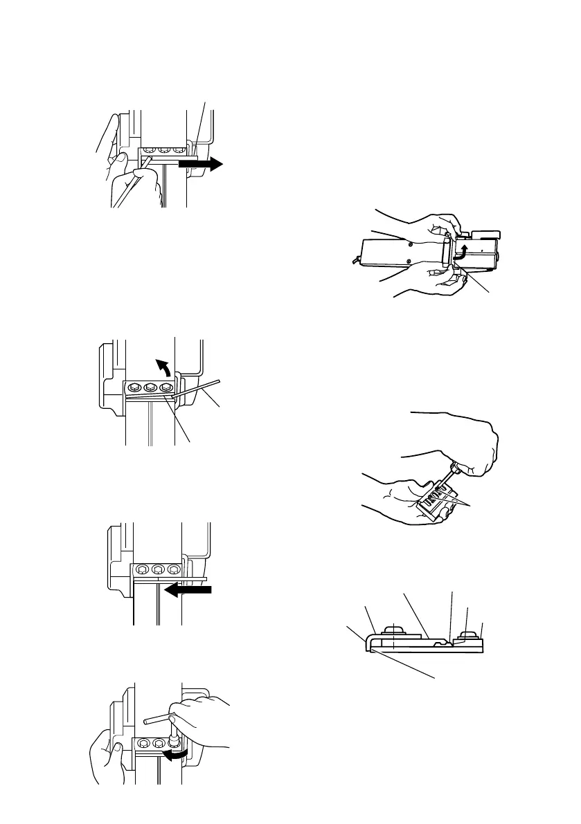
(2) As shown in Fig. 9, after removing the carbide blade,
slide set plate (B) in the direction indicated by the
arrow to disassemble set plate (B).
Fig. 9
(3) Loosen the 2 screws holding on the carbide blade
and set plate (A), set plate (B).
(4) As shown in Fig. 10, 11, press the turned surface of
set plate (A) to the wall surface (B) while adjusting
the carbide blade edge to the wall surface a of the set
gauge. Then, tighten them with the 2 screws.
Fig. 10
Fig. 11
Carbide blade (Double edged blade type)
Carbide blade
(Double edged
blade type)
Set plate (B)
Set plate (B)
Set plate (A)
Set plate (B)
Wall surface b
Turned
surface
Set gauge
Wall surface a
Carbide blade
(Double edged blade type)
Machine screw
01Eng_P20SB_Eng 12/26/08, 10:314
 Loading...