6
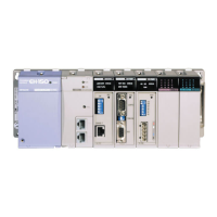
I/O data types
Hitachi PLC’s handles the following I/O.
Bit
(for Digital data, etc)
Word
(for Analog data, etc)
Double Word
Input X ¨¨¨¨ [D] WX ¨¨¨ [H] DX ¨¨¨ [H]
External
I/Os
Output Y ¨¨¨¨ [D] WY ¨¨¨ [H] DY ¨¨¨ [H]
Normal memory R ¨¨¨¨ [H] WR ¨¨¨ [H] DR ¨¨¨ [H]
Shared memory M ¨¨¨¨ [H] WM ¨¨¨ [H] DM ¨¨¨ [H]
Link memory L ¨¨¨¨ [H] WL ¨¨¨ [H] DL ¨¨¨ [H]
Timer (TD,SS, etc.) TD ¨¨¨ [D] - -
Counter (CU, etc.) CU ¨¨¨ [D] - -
Edge detection á DIF ¨¨¨ [D] - -
Internal
I/Os
Edge detection â DFN ¨¨¨ [D] - -
Note : [D] ... Decimal (ex. 00,01,...,09,10,...,15,16,17,18,19,20,21,...)
[H] ... Hexadecimal (ex. 00,01,...,09,0A,0B,...0F,10,11,...1F,20,21,...)
n
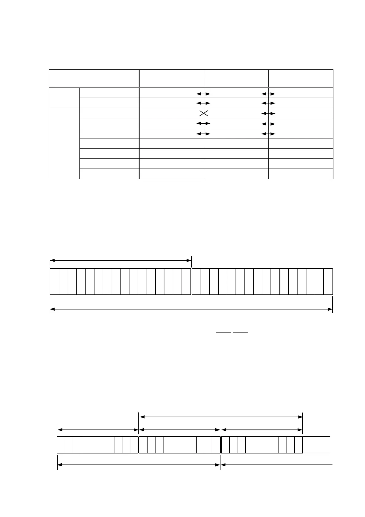
Bit, Word and Double Word
Double Word consists of 2 Words, and 1 Word consists of 16 bits as below.
n
External I/O
External I/Os (X, Y, WX, WY, etc.) are direct addresses for each digital input/output module or analog
input/output module. Please note bit I/Os X and Y are decimal expression.
(WX/WY can be used as access command or data for high function modules like the counter
module.)
X
0
WX 0
X
1
X
2
X
13
X
14
X
15
X
16
WX 1
X
17
X
18
X
29
X
30
X
31
X
32
WX 2
X
33
X
34
X
45
X
46
X
47
DX 0
DX 1
DX 2
B
i
t
15
B
i
t
14
B
i
t
13
B
i
t
12
B
i
t
11
B
i
t
10
B
i
t
9
B
i
t
8
B
i
t
7
B
i
t
6
B
i
t
5
B
i
t
4
B
i
t
3
B
i
t
2
B
i
t
1
B
i
t
0
Word (16 bits)
B
i
t
15
B
i
t
14
B
i
t
13
B
i
t
12
B
i
t
11
B
i
t
10
B
i
t
9
B
i
t
8
B
i
t
7
B
i
t
6
B
i
t
5
B
i
t
4
B
i
t
3
B
i
t
2
B
i
t
1
B
i
t
0
Double Word (32 bits)
Example : WR 0 = H’1234, WR 1 = H’5678 è DR 0 = H’5678 1234
WR 1 WR 0