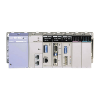
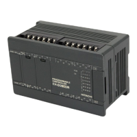
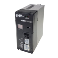
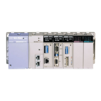
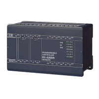
Do you have a question about the Hitachi EH-150 and is the answer not in the manual?
Information on repairs outside the warranty period and for non-warranty covered damages.
Details required when contacting for repair or inquiries.
Safety considerations and instructions for installing the product.
Critical safety warnings for dangerous circumstances and mechanical damage.
Critical safety warnings related to battery handling and potential hazards.
Overview of the Automatic Sending/Receiving function.
How EH-ETH2 automatically sends data.
How EH-ETH2 automatically receives data.
Steps to establish a connection for data communication.
Procedures for establishing TCP/IP connections (active/passive).
Procedures for closing TCP/IP connections.
How to use the optional receiving mode for data storage.
Sending data at requested timing using event sending.
Information on communication status for each ASR connection.
Details of the module status register bits.
Error status for each connection (1 to 6).
Communication status for each connection (1 to 6).
Registers used to control module operations and ASR functions.
Details of the module control register bits for settings and clearing.
Register for controlling open/close requests for connections.
Register for clearing error bits related to send timeout and open errors.
Register for clearing error bits related to receive area and receive errors.
Register for clearing error bits related to send errors.
Register for choosing handling of close requests from other stations.
Procedures for accessing registers using dedicated commands.
Specification and usage of the FUN201 command.
Specification and usage of the SCRW command.
Summary and usage examples for FUN201 command processing.
Example program for reading status registers on EH-CPU.
Example program for writing to control registers on EH-CPU.
How to perform a software reset using FUN201 or SCRW commands.
Details of the WX data register bits.
Details of the WY data register bits for resets and error clearing.
Daily checks for module operation.
Periodic checks for module maintenance.
Interpreting LED indications for errors.
Interpreting LED indications to confirm errors.
Methods to turn off ERR and IER LEDs.
Turning off LEDs using user program on EH-CPU.
Turning off LEDs using user program on EHV-CPU.
Confirming errors by checking the Status Register.
Status information stored in the CPU module's special internal outputs.
Step-by-step guide for diagnosing system issues.
Startup troubleshooting for EH-CPU516/548.
Startup troubleshooting for specific EH-CPU models.
Troubleshooting related to various settings, including dip switches and network.
Troubleshooting flow based on the ERR LED status.
Troubleshooting steps for connection open errors in ASR and task code connections.
Troubleshooting for send errors, especially related to cyclic time.
Function to check communication circuits of EH-ETH2.
Initial checks and material verification before using the module.
Product overview and its role in information networks.
Key capabilities and advantages of the EH-ETH2 module.
Important considerations for using the module with specific CPUs.
Definitions of terms and abbreviations used in the manual.
General technical specifications of the module.
Performance details of the module.
Functional capabilities of the module.
Identification and function of physical components of the module.
How to set and change the operating modes using dip switches.
Meaning of the LEDs on the module for status indication.
Detailed explanation of the STS LED blinking patterns and error codes.
Essential parameters for Ethernet communication setup.
Configuring parameters via the dedicated software.
Required network settings for the PC.
Configuring parameters using dip switches in Configuration mode.
How to connect to and access the EH-ETH2 Configurator software.
Overview of the EH-ETH2 Configurator's main interface elements.
Detailed configuration options within the Ethernet parameters window.
Configuring Ethernet parameters using a user program.
Settings for Automatic Sending/Receiving (ASR) parameters.
General settings applicable to all ASR connections.
Setting up ASR connections between stations.
Specifying I/O areas for sending and receiving data in ASR connections.
Procedures for downloading and uploading configuration setup files.
List of error codes related to ASR parameter settings and their causes.
Detailed specifications for H/EH series communication.
Overview of H/EH series communication protocols and functions.
Structure and format of task code communication frames.
Rules for specifying CPU addresses in the H/EH series network.
Details on logical ports for task code communication (TCP/UDP).
Connecting and configuring for programming with LADDER EDITOR.
Connecting and configuring for programming with Control Editor.
Response time data for task code communication.
Response time data for ASR communication.
Explanation of task code functions and response commands.
A comprehensive list of task codes, their classifications, and descriptions.
Task code for reading CPU status and related information.
Task code for controlling CPU run/stop states.
Task code for managing CPU occupancy and cancellation.
Task code for forcing cancellation of CPU occupancy.
Task code for setting or reading the CPU's internal calendar clock.
Task code for clearing user memory areas.
Task code for transferring program steps to user memory.
Task code for writing memory assignment information.
Task code to notify CPU of parameter area modification.
Task code for modifying timer/counter set values.
Task code for reading program steps by address.
Task code for searching the final ladder circuit.
Task code for reading assigned memory capacity.
Task code for monitoring continuous I/O points.
Task code for forcing set/reset on continuous I/O points.
Task code for monitoring random I/O points.
Task code for forcing set/reset on random I/O points.
Task code for monitoring continuous I/O points.
Task code for forcing set/reset on continuous I/O points.
Task code for monitoring random I/O points.
Task code for forcing set/reset on random I/O points.
A table listing response codes, return codes, and error causes for task codes.
Explanation of IP address structure, classes, and private addressing.
How subnet masks define network and host portions of IP addresses.
How IP packets are sent and routed, and the role of routers.
Overview of the UDP protocol and its characteristics.
Overview of the TCP protocol, connection types, and stream data.
The role of port numbers in network communication.
| Brand | Hitachi |
|---|---|
| Model | EH-150 |
| Category | Controller |
| Language | English |
