Chapter 6 Task code communication
6.1.3 H/EH series network address
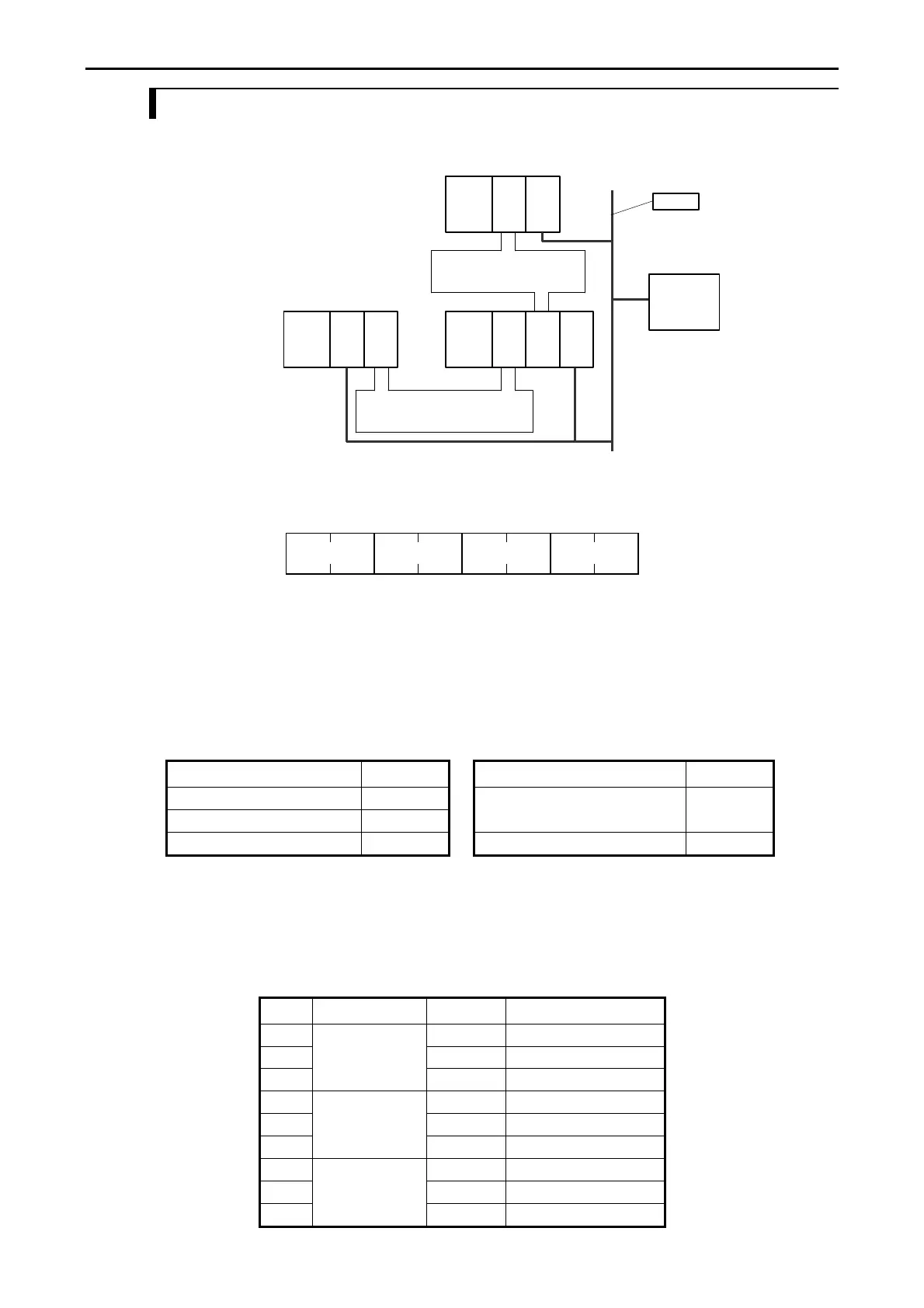
At H/EH series network system shown in Figure 6.3, you must specify the CPU address according to the
LUMP address rule as below.
LNK
CPU
1
LNK
CPU
2
Loop
LNK
Loop
LNK
CPU
3
ETH2
2
Host
Station 0
Station 0
Station 5
Station 1
ETH2
1
ETH2
3
Ethernet
Figure 6.3 Example of H/EH-series network system
Network address configuration is below.
L U M P
L: Loop No. (CPU link number)
U: Unit No. (CPU link station number)
M: Module No.
P: Port No.
Figure 6.4 Network address
Table 6.1 Network address detail
(1) Loop No.(L) (2) Unit No.(U)
Item Loop No. Item Unit No.
CPU LINK loop1 01H CPU LINK ST No.0 00H
CPU LINK loop2 02H CPU LINK ST No.63 3FH
Without CPU LINK FFH Without CPU LINK FFH
(Note) When loop No. is FFH, Unit No. must be FFH. Even the reverse is similar.
(3) Module No. (M) (4) Port No. (P)
Always "00H" Always "00H"
Table 6.2 shows the example of network address setting in Figure 6.3.
Table 6.2 Example of network address setting
No. Via EH-ETH2 CPU Network address
1 CPU1 HFFFF0000
2 CPU2 H01010000
3
ETH2 1
CPU3 (No access)
4 CPU1 H02000000
5 CPU2 HFFFF0000
6
ETH2 2
CPU3 H01000000
4 CPU1 (No access)
5 CPU2 H01050000
6
ETH2 3
CPU3 HFFFF0000
6-3

 Loading...