EasyManua.ls Logo

Hitachi RAK-25PEB User Manual

Hitachi RAK-25PEB
111 pages
To Next Page IconTo Next Page
Page #1 background imageLoading...
Page #1 background image
SPECIFICATIONS AND PARTS ARE SUBJECT TO CHANGE FOR IMPROVEMENT
ROOM AIR CONDITIONER
INDOOR UNIT + OUTDOOR UNIT
SERVICE MANUAL
REFER TO THE FOUNDATION MANUAL
TECHNICAL INFORMATION
FOR SERVICE PERSONNEL ONLY
SPECIFICATIONS
CONTENTS
SPECIFICATIONS ------------------------------------------------------------------- 6
HOW TO USE ----------------------------------------------------------------------- 9
CONSTRUCTION AND DIMENSIONAL DIAGRAM --------------------- 17
MAIN PARTS COMPONENT --------------------------------------------------- 20
WIRING DIAGRAM ---------------------------------------------------------------- 22
CIRCUIT DIAGRAM --------------------------------------------------------------- 24
After installation
BLOCK DIAGRAM ----------------------------------------------------------------- 27
BASIC MODE ----------------------------------------------------------------------- 28
REFRIGERATING CYCLE DIAGRAM --------------------------------------- 38
DESCRIPTION OF MAIN CIRCUIT OPERATION ----------------------- 43
SERVICE CALL Q & A ---------------------------------------------------------- 68
TROUBLE SHOOTING ----------------------------------------------------------- 72
PARTS LIST AND DIAGRAM --------------------------------------------------104
HHAW
RAK-18PEB/RAC-18WEB
RAK-25PEB/RAC-25WEB
RAK-35PEB/RAC-35WEB
RAK-50PEB/RAC-50WEB
INDOOR UNITOUTDOOR UNIT
INDOOR UNIT OUTDOOR UNIT INDOOR UNIT OUTDOOR UNIT INDOOR UNIT OUTDOOR UNIT INDOOR UNIT OUTDOOR UNIT
RAK-18PEB RAC-18WEB
RAK-25PEB
RAC-25WEB
RAK-35PEB
RAC-35WEB
RAK-50PEB
RAC-50WEB
RAK-25PEBC RAK-35PEBC RAK-50PEBC
(KW)
(B.T.U./h)
(KW)
(B.T.U./h)
W 780 660(+60) 780 660(+60) 780 660(+60) 780 792(+91)
H 280 530 280 530 280 530 280 600
D 218 278(+35) 218 278(+35) 218 278(+35) 218 299(+47)
MODEL
POWER SOURCE
TOTAL INPUT (W
TOTAL AMPERES (A)
CAPACITY
COOLING
HEATING
TOTAL INPUT (W
TOTAL AMPERES (A)
CAPACITY
1,090 (250
1,460)
DIMENSIONS
(mm)
1,560 (500 2,100)
3.00-2.97
2.00 (0.90
2.50)
6,820 (3,070
8,530)
620 (250
970)
2.50 (0.90
3.20)
3.52-3.37
7.5
8,530 (3,070
10,920)
880 (250
1,250)
NET WEIGHT (Kg)
TYPE
DC INVERTER
1 PHASE,50HZ,220-230V 1 PHASE,50HZ,220-230V 1 PHASE,50HZ,220-230V 1 PHASE,50HZ,220-230V
580 (
700 (250)010,1 1,290)
4.65-4.44
3.40 (0.90
4.40)
11,600 (3,070
15,010)
5.57-5.33
1,100 (250
1,700)
5.63-5.39
14,330 (3,070
17,060)
3.87-3.70
2.50 (0.90
3.10)
8,530 (3,070
10,580)
7.29-6.85
3.50 (0.90
4.00) 5.00 (1.90 5.20)
11,940 (3,070
13,650) 17,060 (6,480 17,740)
20,470 (7,510
24,910)
7.56-7.23
1,660 (500
2,750)
4.20 (0.90
5.00) 6.00 (2.20 7.30)
25
0
Hitachi Household Appliances(Wuhu) Co., Ltd.
RAK-18PEB
CBEP52-KAR /BEP52-KAR
RAK-35PE
CBEP05-KAR /BEP05-KAR
CBEP53-KAR /B
RAC-18WEB
RAC-25WEB
RAC-35WE
RAC-50WEB
B
0076E-
5.725.72 5.725.7 045.7 8
L.H
PROCEDURE FOR DISASSEMBLY AND REASSEMBLY------------- 40
RAK-25PEBC/RAC-25WEB
RAK-35PEBC/RAC-35WEB
RAK-50PEBC/RAC-50WEB
5
Question and Answer IconNeed help?

Do you have a question about the Hitachi RAK-25PEB and is the answer not in the manual?

Hitachi RAK-25PEB Specifications

General IconGeneral
BrandHitachi
ModelRAK-25PEB
CategoryAir Conditioner
LanguageEnglish

Summary

SPECIFICATIONS OVERVIEW

SAFETY DURING REPAIR WORK

General Repair Safety Guidelines

Essential safety procedures to follow during unit repair and maintenance.

SEMICONDUCTOR HANDLING STANDARDS

Scope and Object Parts

Defines semiconductors and scope for safe handling standards.

Safe Handling Procedures

Outlines procedures for safely handling semiconductor components.

OPERATIONAL CAUTIONS

Important Operating Precautions

Advises on safe operation conditions and potential issues like noise or frost.

DETAILED SPECIFICATIONS

INSTALLATION GUIDELINES

Indoor and Outdoor Unit Placement

Illustrates correct placement and clearances for indoor and outdoor units.

REMOTE CONTROLLER OVERVIEW

Button Functions and Signal Transmission

Explains the functions of each button and the remote's signal transmission.

ADVANCED OPERATION MODES

Leave Home and Powerful Operation Modes

Details the Leave Home and Powerful operation modes for enhanced control.

ENERGY SAVING AND AIRFLOW ADJUSTMENT

Eco Operation

Describes the energy-saving Eco operation mode for reduced power consumption.

Airflow Direction Adjustment

Explains how to adjust the vertical and horizontal airflow direction.

COMPREHENSIVE SAFETY PRECAUTIONS

Precautions During Operation

Safety guidelines to follow while the unit is in operation.

Precautions During Installation

Safety guidelines to follow during the installation process.

Precautions During Maintenance/Shifting

Safety guidelines for unit maintenance and relocation.

COMPONENT IDENTIFICATION

Indoor Unit Parts Description

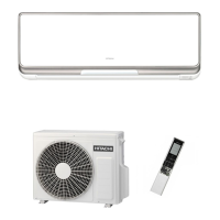
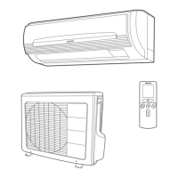
Identifies and describes the parts of the indoor unit.

Outdoor Unit Parts Description

Identifies and describes the parts of the outdoor unit.

ROUTINE MAINTENANCE PROCEDURES

Air Filter Cleaning

Step-by-step guide for cleaning the air filter to maintain performance.

Front Panel Cleaning

Instructions for cleaning the front panel of the indoor unit.

Long-Term Storage Preparation

Procedure for preparing the unit for extended periods of non-operation.

PRODUCT INFORMATION AND SUPPORT

Unit Capabilities

Information on heating and cooling capabilities and limitations.

Regular Inspection Checklist

Points to check during regular periodic inspections of the unit.

After-Sales Service and Warranty

Guidance on what to check before requesting service or warranty claims.

CONSTRUCTION AND DIMENSIONAL DIAGRAMS

Indoor Unit Dimensions

Provides detailed dimensions and clearances for the indoor unit.

CONSTRUCTION AND DIMENSIONAL DIAGRAMS

Outdoor Unit Dimensions (RAC-18/25/35WEB)

Provides detailed dimensions and clearances for RAC-18/25/35WEB outdoor units.

CONSTRUCTION AND DIMENSIONAL DIAGRAMS

Outdoor Unit Dimensions (RAC-50WEB)

Provides detailed dimensions and clearances for the RAC-50WEB outdoor unit.

MAIN PARTS COMPONENT SPECIFICATIONS

Thermostat, Fan Motor, and Outdoor Components

Details specifications for key internal components like thermostats and motors.

COMPRESSOR MOTOR SPECIFICATIONS

WIRING DIAGRAMS

Indoor and Outdoor Unit Wiring Schematics

Shows the electrical connections for both indoor and outdoor units.

PRINTED WIRING BOARD DIAGRAM

CIRCUIT DIAGRAMS

RAK Series Circuit Diagrams

Provides circuit diagrams for RAK series indoor units.

CIRCUIT DIAGRAMS

RAC-18/25/35WEB Circuit Diagram

Provides the circuit diagram for RAC-18/25/35WEB outdoor units.

CIRCUIT DIAGRAMS

RAC-50WEB Circuit Diagram

Provides the circuit diagram for the RAC-50WEB outdoor unit.

SYSTEM BLOCK DIAGRAM

Indoor and Outdoor Unit Interaction

Shows the functional blocks and data flow between indoor and outdoor units.

BASIC OPERATION MODES

Cooling, Dehumidifying, and Heating Modes

Explains the basic operation of Cooling, Dehumidifying, and Heating modes.

MODE DATA PARAMETERS

BASIC COOLING OPERATION DETAILS

SPECIFIC COOLING OPERATIONS

Cooling Defrost Process

Explains the cooling defrost cycle and its timing.

Cooling Powerful Operation

Details the cooling powerful operation mode and its parameters.

DEHUMIDIFYING OPERATION

DEHUMIDIFYING POWERFUL OPERATION

BASIC HEATING OPERATION DETAILS

HEATING DEFROSTING PROCESSES

Reversing Valve Defrosting

Explains the defrosting process using the reversing valve.

Setting Defrosting Inhibit Period

Describes how to set the inhibit period for defrosting cycles.

SPECIFIC HEATING OPERATIONS

Heating Powerful Operation

Details the heating powerful operation mode and its parameters.

Leave Home Operation

Explains the Leave Home operation mode for heating efficiency.

ECO OPERATION MODE

REFRIGERATING CYCLE DIAGRAMS

Cooling Cycle Diagram

Illustrates the refrigerant flow during cooling operation.

Heating Cycle Diagram

Illustrates the refrigerant flow during heating operation.

DISASSEMBLY AND REASSEMBLY PROCEDURES

Indoor Unit Front Panel and Cover Removal

Steps for removing the front panel and cover of the indoor unit.

Indoor Unit P.W.B. Removal

Instructions for removing the control and indicating P.W.B.s from the indoor unit.

DISASSEMBLY AND REASSEMBLY PROCEDURES

Indoor Unit Fan Motor Removal

Steps for removing the tangential fan and fan motor from the indoor unit.

Outdoor Unit Electrical Parts Removal

Instructions for removing electrical parts from the outdoor unit.

DISASSEMBLY AND REASSEMBLY PROCEDURES

Outdoor Unit Electrical Parts Removal

Continued instructions for removing electrical parts from the outdoor unit.

MAIN CIRCUIT OPERATION DESCRIPTION

Control Power Circuit Explanation

Describes the operation of the control power circuit and its components.

RESET CIRCUIT DESCRIPTION

INDOOR FAN MOTOR DRIVE CIRCUIT

MISCELLANEOUS CIRCUIT DESCRIPTIONS

Buzzer Circuit

Describes the operation of the buzzer circuit.

Remote Control Reception Circuit

Explains how the remote control signals are received and processed.

CONTROL CIRCUIT DETAILS

Initial Setting & Temporary Switch Circuits

Describes circuits for initial setup and temporary manual operation.

Thermistor Circuits

Details the room temperature and heat exchanger thermistor circuits.

DIP-SWITCH CONFIGURATION

INDOOR/OUTDOOR COMMUNICATION CIRCUITS

STEPPING MOTOR DRIVE CIRCUIT

POWER CIRCUIT (HIGH VOLTAGE)

POWER CIRCUIT (LOW VOLTAGE)

POWER CIRCUIT BOARD DETAILS

REVERSING VALVE CONTROL CIRCUIT

TEMPERATURE DETECTION CIRCUIT

ELECTRIC EXPANSION VALVE CIRCUIT

OUTDOOR DC FAN MOTOR CONTROL

OUTDOOR FAN MOTOR TROUBLESHOOTING

SERVICE CALL Q&A

Cooling & Dehumidification Issues

Addresses common questions and answers for cooling and dehumidification modes.

Heating & Auto-Fresh Defrost Issues

Addresses common questions and answers for heating and defrost modes.

Automatic Operation Issues

Answers questions regarding automatic operation behavior.

SERVICE CALL Q&A (COMMON ISSUES)

Wind Speed and Noise Issues

Addresses questions about wind speed changes and operational noise.

Temperature Control and Mold Issues

Answers questions on temperature control accuracy and mold prevention.

WIRELESS REMOTE CONTROL TROUBLESHOOTING

Timer Setting and Display Issues

Solves problems related to setting and displaying timers on the remote control.

WIRELESS REMOTE CONTROL TROUBLESHOOTING

Operation Mode and Display Issues

Addresses issues with operation mode settings and remote display feedback.

TROUBLESHOOTING INSPECTION INSTRUCTIONS

POWER CIRCUIT SAFETY PROCEDURES

INDOOR UNIT ELECTRIC PARTS STRUCTURE

Removing Electrical Parts Covers

Steps for removing the electrical parts cover on the indoor unit.

Removing P.W.B.s

Instructions for detaching the control and indicating P.W.B.s.

CONNECTOR HANDLING INSTRUCTIONS

TROUBLESHOOTING SUPPORT (SELF-DIAGNOSIS)

Self-Diagnosis Display Overview

Explains how self-diagnosis information is displayed on the unit.

Self-Diagnosis Memory Function

Details the storing and retrieving of failure modes.

SELF-DIAGNOSIS INDICATIONS (INDOOR)

Counting Lamp Blinking Frequency

How to interpret the blinking frequency of the indoor unit's timer lamp.

Indoor Displayed Fault Codes

Lists fault codes indicated by the indoor unit's timer lamp blinking patterns.

SELF-DIAGNOSIS LIGHTING MODE (RAC-18/25/35WEB)

SELF-DIAGNOSIS LIGHTING MODE (RAC-50WEB)

FORCED COOLING OPERATION

GENERAL TROUBLESHOOTING FLOW

INDOOR UNIT ELECTRICAL PARTS CHECK

FAILURE PHENOMENA: NO POWER

FAILURE PHENOMENA: NO REMOTE SIGNAL

REMOTE CONTROL SIGNAL JAMMING

Interference from Lighting Equipment

Identifies and addresses interference from lighting equipment.

Interference from Other Equipment

Addresses interference from other electronic devices and remote controls.

REMOTE CONTROL SIGNAL JAMMING

Interference from Other Electrical Products

Addresses interference from electrical products and grounding issues.

Grounding and Radio Wave Interference

Addresses interference from grounding, radio waves, and sunlight.

Sunlight Interference

Addresses interference caused by direct sunlight on the receiver.

FAILURE PHENOMENA: COMPRESSOR FAILS TO RUN

FAILURE PHENOMENA: FAN MOTOR DOES NOT STOP

TIMER LAMP BLINKING CODES

Blinking Once, Twice, Three, Four Times

Explains error codes indicated by blinking once, twice, three, or four times.

TIMER LAMP BLINKING CODES

Blinking 9 Times

Explains the error code indicated by the timer lamp blinking 9 times.

TIMER LAMP BLINKING CODES

Blinking 10 Times

Explains the error code indicated by the timer lamp blinking 10 times.

TIMER LAMP BLINKING CODES

Blinking 12 and 13 Times

Explains error codes indicated by blinking 12 or 13 times.

OUTDOOR UNIT ELECTRICAL PARTS CHECK

OUTDOOR UNIT SELF-DIAGNOSIS (LD301)

LD301 Blinking Codes (RAC-18/25/35WEB)

Interprets LD301 blinking codes for RAC-18/25/35WEB units.

OUTDOOR UNIT SELF-DIAGNOSIS (LD301)

LD301 Blinking Codes (RAC-50WEB)

Interprets LD301 blinking codes for RAC-50WEB units.

OUTDOOR UNIT FAULT DIAGNOSIS

Power Supply Voltage Error (LD301 Blinks 10)

Diagnoses power supply voltage errors indicated by LD301 blinking 10 times.

Thermistor Abnormality (LD301 Blinks 7)

Diagnoses thermistor abnormalities indicated by LD301 blinking 7 times.

OH Thermistor Heat-up (LD301 Blinks 6)

Diagnoses OH thermistor heat-up indicated by LD301 blinking 6 times.

High Load Stop (LD301 Blinks 16)

Diagnoses high load stop indicated by LD301 blinking 16 times.

OUTDOOR UNIT FAULT DIAGNOSIS

Overload Lower Limit Cut (LD301 Blinks 5)

Diagnoses overload lower limit cut indicated by LD301 blinking 5 times.

Switchover Failure (LD301 Blinks 4)

Diagnoses switchover failures indicated by LD301 blinking 4 times.

Abnormally Slow Rotation (LD301 Blinks 3)

Diagnoses slow rotation issues indicated by LD301 blinking 3 times.

Peak Current Cut (LD301 Blinks Twice)

Diagnoses peak current cut indicated by LD301 blinking twice.

OUTDOOR UNIT FAULT DIAGNOSIS

Active Voltage Abnormal (LD301 Blinks 14)

Diagnoses active voltage abnormalities indicated by LD301 blinking 14 times.

Fan Lock Stopped (LD301 Blinks 12)

Diagnoses fan lock stop indicated by LD301 blinking 12 times.

Fan Stopped Due to Strong Wind (LD301 Blinks 11)

Diagnoses fan stop due to strong wind indicated by LD301 blinking 11 times.

REMOTE CONTROLLER INTERFERENCE SETTINGS

SHIFT VALUE SETTING ADJUSTMENT

REFRIGERATING CYCLE CHECK PROCEDURE

OUTDOOR UNIT TEST SWITCH OPERATION

INDEPENDENT OUTDOOR UNIT OPERATION

PARTS LIST AND DIAGRAMS

Indoor Unit Parts

A list and exploded view of parts for the indoor unit.

PARTS LIST AND DIAGRAMS

Outdoor Unit Parts (RAC-18/25/35WEB)

A parts list for RAC-18/25/35WEB outdoor units.

PARTS LIST AND DIAGRAMS

Outdoor Unit Parts (RAC-50WEB)

A parts list for the RAC-50WEB outdoor unit.

Related product manuals