EasyManua.ls Logo

Hitachi RAM-52QH5 User Manual

Hitachi RAM-52QH5
104 pages
To Next Page IconTo Next Page
Page #1 background imageLoading...
Page #1 background image
RAM-52QH5
RAM-53QH5
NO. 0428E
SPECIFICATIONS AND PARTS ARE SUBJECT TO CHANGE FOR IMPROVEMENT
ROOM AIR CONDITIONER
OUTDOOR UNIT
AUGUST 2008
Refrigeration & Air-Conditioning Division
SERVICE MANUAL
PM
REFER TO THE FOUNDATION MANUAL
TECHNICAL INFORMATION
FOR SERVICE PERSONNEL ONLY
CONTENTS
SPECIFICATIONS ------------------------------------------------------------------- 5
INSTALLATION --------------------------------------------------------------------- 14
CONSTRUCTION AND DIMENSIONAL DIAGRAM --------------------- 21
MAIN PARTS COMPONENT --------------------------------------------------- 23
CAPACITY DIAGRAM ------------------------------------------------------------ 25
WIRING DIAGRAM ---------------------------------------------------------------- 33
CIRCUIT DIAGRAM --------------------------------------------------------------- 37
BLOCK DIAGRAM ----------------------------------------------------------------- 43
BASIC MODE ----------------------------------------------------------------------- 45
REFRIGERATING CYCLE DIAGRAM --------------------------------------- 71
DESCRIPTION OF MAIN CIRCUIT OPERATION ----------------------- 75
TROUBLE SHOOTING ---------------------------------------------------------- 106
DISASSEMBLY AND REASSEMBLY --------------------------------------- 113
PARTS LIST AND DIAGRAM ------------------------------------------------- 116
RAM-52QH5
RAM-53QH5
After installation
NOTE:
This manual describes only points that differ from RAF-25, 35,
50NH5, RAD-25, 35NH5, RAD-25, 35NH5 and RAM-80QH5
(TC No. 0771EF), RAI-25, 35NH5 (PM No. 0271E), RAI-50NH5
and RAC-50NH5 (PM No. 0274E), RAK-18, 25, 35NH5 (PM
No. 0269E), RAK-50NH5 and RAC-50NH5 (PM No. 0302E)
for items not described in this manual.
850
650
298
50
(W)
(A)
COOLING CAPACITY
DC INVERTER DUAL AND TRIPLE SYSTEM MULTI
TYPE
MODEL
POWER SOURCE
TOTAL INPUT
TOTAL AMPERES
SPECIFICATIONS
OUTDOOR UNIT
RAM-52QH5
HEATING CAPACITY
DIMENSIONS (mm)
NET WEIGHT
1ø, 220 - 240V, 50Hz
W
H
D
(kg)
(kW)
(B.T.U.)
REFER TO THE SPECIFICATIONS PAGE
RAM-53QH5

Table of Contents

Other manuals for Hitachi RAM-52QH5

Question and Answer IconNeed help?

Do you have a question about the Hitachi RAM-52QH5 and is the answer not in the manual?

Hitachi RAM-52QH5 Specifications

General IconGeneral
BrandHitachi
ModelRAM-52QH5
CategoryAir Conditioner
LanguageEnglish

Summary

Safety During Repair Work

Essential Safety Precautions

Critical safety guidelines for service personnel to follow during repair operations.

Wiring Diagram

RAM-52QH5 Outdoor Unit Wiring

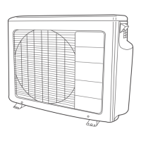
Schematic showing electrical connections for the RAM-52QH5 outdoor unit.

RAM-53QH5 Outdoor Unit Wiring

Schematic showing electrical connections for the RAM-53QH5 outdoor unit.

Expansion Valve and Compressor Control

RAM-52QH5 Valve and Compressor Logic

Explanation of expansion valve initialization and compressor speed control for RAM-52QH5.

Defrost Operation

Defrost Cycle Conditions

Criteria for initiating and releasing the defrost cycle, including temperature thresholds.

Auto-Fresh Defrost

RAM-52QH5 Auto-Fresh Conditions

Steps and conditions required for the auto-fresh defrost feature on RAM-52QH5.

Forced Cooling Operation

RAM-52QH5 Forced Cooling Process

Description of forced cooling execution conditions and operational status for RAM-52QH5.

Overheat Thermistor Processing

RAM-52QH5 High Temp Speed Reduction

Procedures for compressor speed reduction due to high OH temperature on RAM-52QH5.

Refrigerating Cycle Diagram

RAM-52QH5 Cycle Schematics

Diagrams illustrating the refrigerant flow paths for different operating modes.

Main Circuit Operation Description

Power Circuit Functionality

Explanation of the main power circuit, including rectification and voltage boosting.

Interface Circuitry

Description of the circuits enabling communication between indoor and outdoor units.

System Power Module Circuit

Power Module Schematic and Operation

Diagram and explanation of the system power module, including ACT and inverter functions.

Power Supply Circuit

Switching Power Supply Details

Information on the two switching power supplies and their roles in voltage conversion.

Reversing Valve Control Circuit

Reversing Valve Operation Logic

Explanation of reversing valve control based on operating conditions and voltage readings.

Rotor Magnetic Pole Position Detection

Detection Circuit Functionality

Description of the circuit that detects the rotor's magnetic pole position for compressor control.

Overload Control Circuit

Overload Control System Configuration

Diagram and explanation of the overload control system's logic and configuration.

Temperature Detection Circuit

Thermistor Circuit Schematics

Diagrams showing the wiring for temperature detection using various thermistors.

Thermistor Troubleshooting Guide

LED Fault Indicators for Thermistors

Guide to interpreting LED blinking patterns to diagnose thermistor faults.

Electric Expansion Valve Control

Expansion Valve Operation and Waveforms

Details on electric expansion valve operation, including drive status tables and waveforms.

Inspecting Outdoor Electrical Parts

LED Status Interpretation for Faults

Guide to diagnosing electrical issues by checking LED status and related checkpoints.

Troubleshooting Method 1

Inspection Method 1 Flowchart

Step-by-step diagnostic flowchart based on initial checks and LED status.

Troubleshooting Method 2

Inspection Method 2 Flowchart

Diagnostic flowchart focusing on LD301 and LD302 blinking patterns for fault identification.

Troubleshooting Method 3

Troubleshooting Method 4

Troubleshooting Precautions

Power Circuit Discharge Procedure

Self-Diagnosis Lamp Interpretation

Troubleshooting System Power Module

Refrigerating Cycle Troubleshooting

Repairing Refrigerating Cycle Components

Parts List and Diagram

Related product manuals