EasyManua.ls Logo

Hitachi RAM-65QH5 User Manual

Hitachi RAM-65QH5
108 pages
To Next Page IconTo Next Page
Page #1 background imageLoading...
Page #1 background image
RAM-55QH5
RAM-65QH5
NO. 0312E
SPECIFICATIONS AND PARTS ARE SUBJECT TO CHANGE FOR IMPROVEMENT
ROOM AIR CONDITIONER
OUTDOOR UNIT
DECEMBER 2005
Refrigeration & Air-Conditioning Division
SERVICE MANUAL
PM
REFER TO THE FOUNDATION MANUAL
TECHNICAL INFORMATION
FOR SERVICE PERSONNEL ONLY
CONTENTS
SPECIFICATIONS ------------------------------------------------------------------- 5
INSTALLATION --------------------------------------------------------------------- 14
CONSTRUCTION AND DIMENSIONAL DIAGRAM --------------------- 21
MAIN PARTS COMPONENT --------------------------------------------------- 23
CAPACITY DIAGRAM ------------------------------------------------------------ 25
WIRING DIAGRAM ---------------------------------------------------------------- 33
CIRCUIT DIAGRAM --------------------------------------------------------------- 37
BLOCK DIAGRAM ----------------------------------------------------------------- 43
BASIC MODE ----------------------------------------------------------------------- 45
REFRIGERATING CYCLE DIAGRAM --------------------------------------- 71
DESCRIPTION OF MAIN CIRCUIT OPERATION ----------------------- 75
TROUBLE SHOOTING ---------------------------------------------------------- 106
DISASSEMBLY AND REASSEMBLY --------------------------------------- 113
PARTS LIST AND DIAGRAM ------------------------------------------------- 116
RAM-55QH5
RAM-65QH5
After installation
NOTE:
This manual describes only points that differ from RAF-25, 35,
50NH5, RAD-25, 35NH5, RAD-25, 35NH5 and RAM-80QH5 (TC
No. 0771EF), RAI-25, 35NH5 (PM No. 0271E), RAI-50NH5 and
RAC-50NH5 (PM No. 0274E), RAK-18, 25, 35NH5 (PM No.
0269E), RAK-50NH5 and RAC-50NH5 (PM No. 0302E) for items
not described in this manual.
850
650
298
50
(W)
(A)
COOLING CAPACITY
DC INVERTER DUAL SYSTEM MULTI
TYPE
MODEL
POWER SOURCE
TOTAL INPUT
TOTAL AMPERES
SPECIFICATIONS
OUTDOOR UNIT
RAM-55QH5
RAM-65QH5
HEATING CAPACITY
DIMENSIONS (mm)
NET WEIGHT
1ø, 220 - 240V, 50Hz
W
H
D
(kg)
(kW)
(B.T.U.)
REFER TO THE SPECIFICATIONS PAGE

Table of Contents

Question and Answer IconNeed help?

Do you have a question about the Hitachi RAM-65QH5 and is the answer not in the manual?

Hitachi RAM-65QH5 Specifications

General IconGeneral
BrandHitachi
ModelRAM-65QH5
CategoryAir Conditioner
LanguageEnglish

Summary

Safety and Handling Precautions

Safety During Repair Work

General safety guidelines and warnings for service personnel.

Semiconductor Handling Standards

Standards for handling semiconductors to prevent damage.

General Cautionary Notes

Important cautionary notes for operation and maintenance.

Unit Specifications

Outdoor Unit Specifications

Detailed technical specifications for the outdoor unit model.

Indoor Unit Combination Specifications

Specifications for dual system indoor unit combinations.

Indoor Unit Combination Specifications

Specifications for triple system indoor unit combinations.

Capacity Specifications for Indoor Unit Combinations

Dual System Capacity Specifications

Cooling/heating capacity for dual system indoor unit combinations.

Triple System Capacity Specifications

Cooling/heating capacity for triple system indoor unit combinations.

Installation Guidelines

Indoor Unit Combinations for Dual System

Lists compatible indoor units for dual system configuration.

Indoor Unit Combinations for Triple System

Lists compatible indoor units for triple system configuration.

Connecting Positions for Indoor Units (Dual System)

Specifies outdoor unit connection points for dual system.

Connecting Positions for Indoor Units (Triple System)

Specifies outdoor unit connection points for triple system.

Outdoor Unit Installation Details

Guidelines for pipe length, height difference, and mounting.

Construction and Dimensional Diagram

Outdoor Unit Dimensions and Service Space

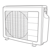
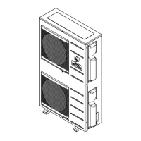
Provides dimensional drawings and required service space for the outdoor unit.

Main Parts Component

Fan Motor and Compressor Specifications

Technical data for fan motor and compressor.

Capacity Diagrams

Capacity vs. Ambient Temperature

Shows cooling and heating capacity based on ambient temperature.

Capacity vs. Piping Length

Illustrates capacity change ratio based on piping length.

Sound Pressure Level

Sound Pressure Level (Heating and Cooling Modes)

Noise level data for heating and cooling operation across frequency bands.

Electrical Diagrams

Wiring Diagram

Detailed wiring schematic for the outdoor unit's electrical connections.

Circuit Diagram

Schematic diagram illustrating the remote control system's circuitry.

Block Diagram

High-level functional blocks of the outdoor unit's system.

Operation Modes

Basic Operation Modes Description

Explains the functions and settings for basic operation modes.

Defrost Operation

Details the conditions required to start and release defrost mode.

Auto-Fresh Defrost

Specifies the conditions necessary for activating auto-fresh defrost.

Forced Cooling Operation

Describes the conditions and operation status for forced cooling.

Overheat Thermistor Processing

Outlines conditions for restricting compressor speed due to overheat.

Refrigerating Cycle Diagrams

Cooling, Dehumidifying, Defrosting Cycle

Schematic of the refrigerant flow for cooling, dehumidifying, and defrosting.

Heating Cycle Diagram

Schematic of the refrigerant flow for heating operation.

Main Circuit Operation Description

Power Circuit Operation

Details the operation of the power circuit including rectifying and boosting.

System Power Module and Power Supply Circuits

System Power Module Circuit

Illustrates the circuit diagram of the system power module.

Power Supply Circuit Details

Explains the functions of the switching power supplies for control and valves.

Control Circuits

Reversing Valve Control Circuit

Describes collector voltage of Q831 under different operation conditions.

Rotor Magnetic Pole Position Detection Circuit

Schematic for detecting the rotor's magnetic pole position for motor control.

Microcomputer Peripheral Circuits

Explains basic operations of peak current cut, overload, and reset circuits.

Overload Control Circuit (OVL Control Circuit)

Details the system configuration for overload control.

Reset Circuit

Describes the reset circuit's function and voltage waveforms.

Temperature Detection Circuit

Thermistor Functions and Connections

Details the role and connection points of various thermistors.

Thermistor Resistance vs. Temperature

Provides reference values for thermistor resistance and corresponding temperatures.

Electric Expansion Valve and Power Factor Control

Electric Expansion Valve Operation

Explains valve drive, switching, and waveform analysis.

Power Factor Control Principle

Describes the control method for achieving high power factor.

Troubleshooting Procedures

Outdoor Unit LED Status and Checkpoints

Guides on interpreting LED indicators for diagnosing issues.

Troubleshooting Inspection Methods

Step-by-step guides for diagnosing and resolving unit malfunctions.

Service Switch Operation

Operating the Outdoor Unit Independently

Instructions for operating the outdoor unit using the service switch.

Disassembly and Reassembly

Electric Parts Disassembly and Reassembly

Step-by-step guide for removing and reinstalling electrical components.

Refrigerating Cycle Component Removal

Instructions for removing expansion valves, condenser, and reversing valve.

Parts List and Diagram

Parts List for RAM-55QH5

Comprehensive list of part numbers and descriptions for RAM-55QH5.

Parts List for RAM-65QH5

Comprehensive list of part numbers and descriptions for RAM-65QH5.

Related product manuals