2. Structure
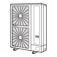
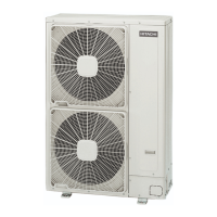
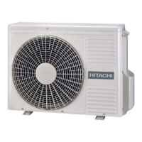
2.1 Name of Parts
< 3HP >
No. Part Name No. Part Name
1 Compressor 13 Check Joint
2 Accumulator 14 Electrical Box
3 Heat Exchanger 15 High Pressure Switch for Protection
4 Propeller Fan
16
Sensor for Refrigerant Pressure
(High Pressure Sensor)
5 Fan Motor
6 Strainer 17 Pressure Switch for Control
7 Distributor 18 Silencer
8 Reversing Valve 19 Crankcase Heater (2pcs.)
9 Micro-Computer Control Expansion Valve 20 Vibration Absorbing Rubber (3pcs.)
10 Solenoid Valve 21 Air Outlet
11 Stop Valve for Gas Line 22 Air Inlet
12
Stop Valve for Liquid Line
1
10
2
4
7
5
9
3
17
19
20
18
14
12
11
15
13
16
6
21
22
6
2
8
22
370
45.5
800
768
32
950
410
440
PCN7 PCN6PCN13PCN14PCN8PCN9
THM7THM8THM9THM10
CN1 CN2
1 62 5
ON
3 41 62 5
ON
3 4
DSW2 DSW4
0
9
8
7
6
5
4
3
2
1
ON
21 1 62 5
ON
3 4
RSW1
DSW6
PSW1
SEG1
1
ON
2 43
TR1
ON
21
IC1
+
REG1
+
C71
LED1
+
C87
C72
Y52C
DSW3
TP1
PSW3
LED2
CN101
EF3
CN406
PCN406
PCN1
R195
PCN100
EF1
LED4
EFS1
EFR1
E
Y21SW1
DM1
Y21SW2-2
Y21SW2-1
CN10
CN404
CN100
PSW2
CN6
LED3
SW1
DSW1
SK1
Y20C
Y20A
Y21
YCH
PCN5PCN10
CN8
DSW5
CN7
CN5A
L1 1 2
L2
N
to DRM1 and SC terminals.
or transmission wiring
Do not connect power supply
17E26270A
CAUTION
SCAS4755 DRM1
CN405
EF2

 Loading...


