Do you have a question about the Hitachi RAS-5HVRNM2 and is the answer not in the manual?
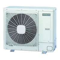
Lists and illustrates the components of the outdoor unit.
Specifies the required tools and instruments for installation.
Guide to selecting the appropriate outdoor and indoor unit model.
Criteria for selecting indoor units in a multi-unit system.
Standard combinations of outdoor and indoor units for various models.
Guidelines for enhanced combinations of outdoor and indoor units.
Lists accessories provided with the outdoor unit.
Pre-installation checks for the outdoor unit.
Specifies required clearances for installation and maintenance.
Details the procedures for securing the unit and fixing it.
Specifies requirements for copper pipes and their preparation.
Instructions on flaring dimensions and joint selection for pipes.
Guidance on selecting pipe sizes based on unit capacity and length.
Details stop valve positions and connection methods.
Procedures for connecting refrigerant pipes and tightening flare nuts.
Checks for electrical components, power supply, and wiring.
Instructions for connecting wiring terminals and cables.
Configuration of DSW1, DSW2, DSW3 for various operational settings.
Settings for outdoor unit number, refrigerant cycle, and terminal resistance.
Procedure for testing piping for leaks using nitrogen gas.
Steps for vacuum pumping and charging refrigerant.
Calculating and adding refrigerant based on piping length.
Pre-checks before initiating the unit's test run.
Procedure for conducting the unit's test run and checking operation.
How to set optional functions via dip switches and menu.
| Cooling Capacity | 5.0 kW |
|---|---|
| Power Supply | 220-240V, 50Hz |
| Refrigerant | R410A |
| Energy Efficiency Ratio (EER) | 3.21 |
| Coefficient of Performance (COP) | 3.61 |
| Type | Split System |


 Loading...