3.3
Installation(3.0~6.5HP)
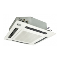
3.3.2 Mounting Position of the Indoor Unit
Installation and Maintenance
15
Model
3.0/4.0
5.0/6.0/6.5
Fig.3.5 Mounting Position
3.3.1 Opening of False Ceiling and Suspension Bolts
(1) Determine the final location of the indoor unit paying careful attentionand direction of installation
to the space for the piping, wiring and maintenance.
Pattern board for installation is printed on the packing. Cut off the pattern for opening the false
ceiling and installation suspension bolts.
(2) Cut out the area for the indoor unit in the false ceiling and install suspension bolts, as shown
in Fig.3.3.
Fig.3.3 Opening of False Ceiling and Suspension Bolts
(3) Check to ensure that the ceiling is horizontally level, otherwise drainage can not flow.
(4) Strengthen the opening parts of the false ceiling.
(5) Mount suspension bolts, as shown in Fig.3.4.
Fig.3.4 Mounting Suspension Bolts
150 to 160mm
I Beam
Suspension Boit (W3/8 or M10)
For Concrete Slab
For steel Beam
Insert
(100 to 150kg)
Concrete
Anchor Bolt
(W3/8 or M10)
(mm)
(4-Suspension Bolts)
M10 or W3/8 (Field-Spplied)
W-Nut (Field Supplied)
Washer (Accessary)
Surface of Ceiling
a
* indicates the dimension between
lower face of indoor unit and
surface of ceiling.
Liquid Pipe Connection
Gas Pipe Connection
(mm)
Drain Pipe Connection
Wiring Hole (ø32.5 Hole)
118 ( Drain Pipe)
(for Spare)
Wiring Hole (30x30)
(for Cable)
127 (Liquid Pipe Connection)
102 (Gas Pipe Connection)
Fig.3.6 Indoor Unit and Air Panel
248
298
 Loading...