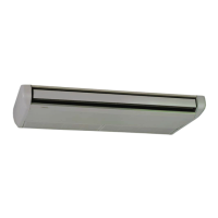
12.3.3 Mounting indoor unit
1 Pattern Board for Installation. The pattern board for the
installation is printed on the packing. When making holes in
wall and ceiling, the pattern board which hole positions for
suspension, refrigerant pipe and drain pipe are printed shall
be used.
Upper cap
The pattern board is attached in
the upper cap.
2 Hanging indoor unit:
• Hanging indoor unit with suspension bracket
a. Make holes in the ceiling for suspension bolts.
b. Remove the side cover.
c. Remove the suspension brackets attached to the indoor
unit.
d. Fix the suspension brackets to the suspension bolts
(4 portions).
e. Mount the indoor unit to the suspension brackets.
f. Tighten the 4 nuts and the xing screw for suspension
bracket.
Suspension bolt
Suspension
bracket
Washer
Nut
Suspension bolt
Max. 50 mm
Nut (accessory) Rear side of
indoor unit
(6 mm)
Ceiling
Suspension bolt
Tighten accessory
4 nuts (M8)
• Hanging indoor unit without suspension bracket
If there is not enough service space between the ceiling and the
indoor unit, hang the indoor unit by method "Hanging indoor unit
with suspension bracket".
a. Determine the position to install the suspension bolt.
b. Fix the washer and nut to the suspension bolt.
c. Mount the indoor unit to the suspension bolts.
Suspension bolt (eld-supplied)
Nut (eld-supplied)
Washer (eld-supplied)
Suspension bolt
Max. 50 mm
Washer (eld-supplied)
Nut (eld-supplied)
Ceiling
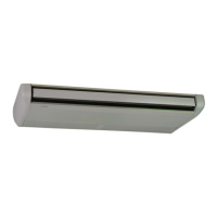
3 When the indoor unit is mounted, create down-slope toward
drain pipe connection to be well drainage. The gure shows
the right drain pipe connection. (Before shipment) For the left
drain pipe connection, create down-slope toward left.
(Drain pipe connection)
from horizontal
View from front
View from right
from horizontal
Lower the indoor unit 10 mm
when the optional drain-up
mechanism is installed.
? NOTE
The ceiling surface may not be horizontal. When the indoor unit is
mounted, check the levelness by a level to be the drain pipe connection
down-slope. If the indoor unit is mounted with incorrect suspending
position, it may deform and the abnormal vibration may occur.
4 Attach the side cover and the supporting string.
5 Remove the protection lm attached to the louver surface.
6 Remove the protection tape attached to the air inlet lter.
INDOOR UNIT INSTALLATION
PMML0551 rev.4 - 07/2023 - A10762310A
16
 Loading...