EasyManua.ls Logo

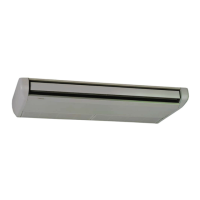
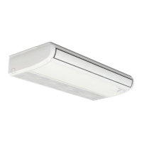
Hitachi RPC-6.0FSN3 User Manual

Hitachi RPC-6.0FSN3
756 pages
To Next Page IconTo Next Page
Page #1 background imageLoading...
Page #1 background image
SET FREE SERIES
FSXN1E
FSXNH(E)
INSTALLATION AND OPERATION MANUAL
MANUAL DE INSTALACIÓN Y FUNCIONAMIENTO
INSTALLATIONS- UND BETRIEBSHANDBUCH
MANUEL D’INSTALLATION ET DE FONCTIONNEMENT
MANUALE D’INSTALLAZIONE E D’USO
MANUAL DE INSTALAÇÃO E DE FUNCIONAMENTO
INSTALLATIONS- OG BETJENINGSVEJLEDNING
INSTALLATIE- EN BEDIENINGSHANDLEIDING
INSTALLATION- OCH DRIFTHANDBOK
ΕΓΧΕΙΡΙΔΙΟ ΕΓΚΑΤΑΣΤΑΣΗΣ ΚΑΙ ΛΕΙΤΟΥΡΓΙΑΣ
PMML0294A_rev.2_02-2014.indb 1 14/07/2014 12:27:46

Other manuals for Hitachi RPC-6.0FSN3

Questions and Answers:

Hitachi RPC-6.0FSN3 Specifications

General IconGeneral
BrandHitachi
ModelRPC-6.0FSN3
CategoryAir Conditioner
LanguageEnglish

Summary

General Information

Unit Installation

Safety

Additional Information About Safety

Important safety precautions regarding electrical shock, handling of safety devices, fire safety, and unit installation.

Automatic Controls

Refrigerant Cycle

Transport, Lifting and Handling of the Units

Installation

Piping Work and Refrigerant Charge

Refrigerant Pipe Selection

Guidelines for selecting refrigerant pipe sizes based on system type, outdoor unit, and connection kits.

Precautions for the Installation of the Outdoor Unit

Guidelines for safe outdoor unit installation, including pipe arrangement and unit sequencing.

General Instructions on the Installation of Refrigerant Pipes

General guidelines for installing refrigerant pipes, including flared connection mounting and insulation.

Refrigerant Pipe Connection for Heat Pump Systems (2 pipes) and Heat Recovery Systems (3 pipes)

Diagrams and tables for connecting refrigerant pipes for heat pump and heat recovery systems.

Additional Refrigerant Charge

Air-Tight Test

Procedure for performing an air-tight test on the refrigerant system using nitrogen gas.

Vacuuming

Steps for vacuum pumping the refrigerant system to remove moisture and air.

Additional Refrigerant Charge Calculation

Method for calculating and adding refrigerant based on piping length and indoor unit capacity.

Charging Work

Procedures for charging additional refrigerant, including cautions and steps for opening stop valves.

Automatic Simple Judgement System for Refrigerant Amount

System for automatically checking refrigerant amount and diagnosing issues like excess, insufficient, or abnormal termination.

Special Attention Regarding Refrigerant Gas Leakage

Safety measures and calculations related to refrigerant gas leakage and permissible concentrations.

Electrical Wiring

Connection of the Power Supply Circuits

Wiring diagrams for connecting power sources to outdoor and indoor units for heat pump and heat recovery systems.

Setting of the DSW Switches on PCB1

Guide to setting DIP switches on the PCB for various functions like refrigerant cycle, capacity, and unit numbering.

Test Run

Preliminary Checks

Essential checks before performing the test run, including safety, wiring, and refrigerant pipe connections.

Carry Out the Test Run

Procedures for conducting the test run, including checking stop valves, sequences, and system conformity.

Test Run Check List

A checklist to verify all parameters and conditions during the test run.

Alarm Codes

Control and Safety Devices

Basic Troubleshooting

Related product manuals