30
INSTALLATION AND OPERATION MANUAL
11.5. CAUTION OF THE PRESSURE BY CHECK
JOINT
When the pressure is measured, use the check joint of gas stop valve (A),
and use the check joint of liquid piping (B) in the gure below.
At that time, connect the pressure gauge according to the following
table because of high pressure side and low pressure side changes by
operation mode.
Cooling
Operation
Heating
Operation
Check Joint for Gas Stop Valve “A” Low Pressure High Pressure
Check Joint for Piping “B” High Pressure Low Pressure
Check Joint for Liquid Stop Valve “C”
Exclussive for Vacuum Pump
and Refrigerant Charge
NOTE:
Be careful that refrigerant and oil do not splash to the electrical parts
at removing the charge hoses.
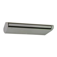
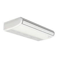
RAS-5H(V)RNM1E
RAS-3HVRNME
The below gures show
examples of 3 and 5 HP
11.6. REFRIGERANT CHARGING QUANTITY
Outdoor Units has been charged with refrigerant for ℓ(m) of actual piping
length. An additional refrigerant charged is required in systems with actual
piping length longer than ℓ(m).
1. Determine an additional refrigerant quantity according to the following
procedure, and charge it into the system.
2. Record the additional refrigerant quantity to facilitate service activities
thereafter.
CAUTION:
When charging refrigerant accurately measure refrigerant to be
charged.
Overcharging or undercharging of refrigerant can cause
compressor trouble
In case of actual piping length less than 5 m, consult your
distributor.
Outdoor unit Factory Refrigerant charge (Wo Kg) is the next:
O/U MODEL Wo (Kg)
Chargeless
Length ℓ(m)
Additional Charge
Factor (P)
RAS-3HVRNME 2.4 30 0.04
RAS-4H(V)RNM1E 3.9 30 0.06
RAS-5H(V)RNM1E 3.8 30 0.06
RAS-6H(V)RNM1E 3.8 30 0.06
RAS-4HVRNS1E 2.8 20 0.04
RAS-5HVRNS1E 2.9 30 0.06
RAS-6HVRNS1E 2.9 30 0.06
a) Refrigerant shall be added if L is longer than the chargeles length
shown in the table above.
Calculate the additional amount as follows:
L= A+B+C= 30+8+8= 46
RCI-2.0FSN2E
RCI-2.0FSN2E
RAS-4HVRNM1E
- Chargeless Length ℓ: for 4HVRNM1E is 30 m according to the
table before.
- Additional Correction Value P: for 4HVRNM1E, “0.06” according to
the table above.
- Additional Charge amount W will be:
W= (L-ℓ) x P = (46-30) x 0.06 = 0.96 (kg)
b) Charge the amount W calculated by a)
c) Setting of Pipe Length DSW.
DSW2 setting will be required only when the refrigerant pipe length
is shorter than 5 m or longer than 30 m. Pipe length setting shall be
performed as shown below.
(The side in the table below shows the DSW location)
DSW2 on Outdoor PCB1
Factory setting Factory setting Factory setting
Pipe Length 5 m or
shorter
Pipe Length 30 m or
longer
11.7. PUMP DOWN REFRIGERANT
When the refrigerant should be collected into the outdoor unit due to
indoor/outdoor unit relocation, collect the refrigerant as follows:
1. Attach the manifold gauge to the gas stop valve and the liquid stop
valve
2. Turn ON the power source
3. Set the DSW1-1 pin of the outdoor unit PCB at the “ON” side
for cooling operation. Close the liquid stop valve and collect the
refrigerant.
4. When the pressure at lower pressure side (gas stop valve) indicates
-0.01 MPa (-100 mmHg), perform the following procedures
immediately.
− Close the gas stop valve.
− Set the DSW1-1 pin at the “OFF” side (To stop the unit operation).
5. Turn OFF the power source.
CAUTION:
Measure the low pressure by the pressure gauge and keep it not to
decrease than -0.01 MPa. If the pressure is lower than -0.01 MPa,
the compressor may be faulty.
PMML0197_r0_04-10.indb 30 08/07/2010 9:20:49
 Loading...