4. Refrigerant Piping
4.1 The Pipe Material
4.2 Piping Connection
(1) The connection positions of the pipe are shown in
Fig. 4.1 and Fig. 4.2.
unit: (mm)
14
Fig. 4.1 The connection positions of the tube
Capacity
(HP)
Gas pipe
Liquid pipe
4.0~6.5
φ19.05
φ9.52
(2) As shown in Fig. 4.3, fix the nuts with 2 spanners.
Fig. 4.3 Torque specifications for Nuts
(3) After completing refrigerant pipe connection, keep
it warm with the insulation material.
φ6.35mm
φ9.52mm
φ12.7mm
φ15.88mm
φ19.05mm
Pipe size
20
40
60
80
100
Torque (N.m)
Fig. 4.4 Piping insulation procedure
Clamp(attached)
Insulation (attached)
Refrigerant pipe
(field supplied)
Side of the
indoor unit
Insulation
(field supplied)
Installation and Maintenance
DANGER
Protected with the tape or plug.
Do not put the pipes directly on
the floor.
·
Do not place the pipes on the floor directly.
3.0
φ15.88
φ9.52
Drain pipe
2.0
φ12.7
φ6.35
De25
De25
De25
Fig. 4.2 The pipe diameter
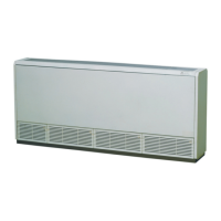
The pipe can be connected from three different
directions. (rear, right, top).
If the pipe is routed from the back side,
remove the brackets for easier piping work.
After piping, reinstall the removed bracket.
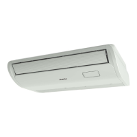
If the pipe is routed from the back side.
Cut the removed top cover, and install on the rear
panel instead of rear cover.
Gas piping
Liquid piping
Drain piping
(right)
Drain piping
(left)
CAUTION
·
The pipe should pass through the hole with a seal.
Use the R410A refrigerant. During leakage check
and test, do not mix oxygen, acetylene and other
flammable or reactive gases. These gases are quite
dangerous, and may possibly cause explosion.
Use compressed air, nitrogen or the refrigerant is
to perform these experiments.
(1) Prepare the copper pipe at the spot.
(2) Choose dustless, non-humid, and clean copper
pipe. Before installing the pipe, use nitrogen or
dry air to blow away the tube dust and impurity.
(3) Choose the copper pipe according to Fig. 4.2.
 Loading...