Do you have a question about the Hitachi RPFI-1.5FSGE and is the answer not in the manual?
Basic troubleshooting steps including switch settings, wiring checks, and emergency operations.
Detailed procedures for troubleshooting based on alarm codes and check modes.
Methods for self-checking PCBs, remote control switch, and other main components.
Procedures for performing test runs using remote control or outdoor unit controls.
Procedures for removing and servicing components of the outdoor unit.
Procedures for servicing components of specific in-the-ceiling indoor units.
Procedures for servicing components of specific in-the-ceiling indoor units.
Procedures for removing and servicing components of 4-way cassette type indoor units.
Procedures for removing and servicing components of 2-way cassette type indoor units.
Procedures for removing and servicing components of wall type indoor units.
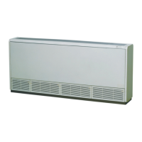
Procedures for removing and servicing components of floor type indoor units.
Procedures for removing and servicing components of floor concealed type indoor units.
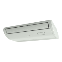
Procedures for removing and servicing components of ceiling type indoor units.
Procedures for servicing the total heat exchanger and its electrical parts and elements.
Procedures and tools required for cleaning indoor unit heat exchangers of various types.
Specifications, protection functions, and arrangement of the inverter power unit.
Concept, features, and specifications of AC Chopper control for fan speed.
Operation and stoppage principles of auto-louver mechanisms for various indoor unit types.
Mechanism, principle of compression, and structure of scroll compressors.
Positions and resistance characteristics of thermistors for indoor and outdoor units.
Specifications and wiring diagrams for electronic expansion valves for outdoor and indoor units.
High pressure and low pressure sensor control mechanisms and output characteristics.
Function and circuit diagram of the high pressure protection device.
Specifications and circuit diagram for the noise filter (NF).
Use and specifications of capacitors for the inverter.
Use and specifications of reactors for the inverter.
Optional functions for indoor units, including remote control ON/OFF and operation modes.
Input/output settings, remote control thermistor, and mode setting changes for specific indoor units.
External signal inputs/outputs, demand control, and fixing operation modes for outdoor units.
Identification of parts and operation system for remote control switches.
Identification of parts and procedures for simultaneous operation of wireless remote controls.
Operation and indications of the 7-day timer (PSC-5T).
Overview of the central station (PSC-5S) and its operation.
Field work example and countermeasure for compressor burnout from insufficient refrigerant.
Field work example and countermeasure for poor cooling due to long piping.
Field work example and countermeasure for abnormal operating sound in ceiling units.
Field work example and countermeasure for system stoppage due to alarm code "31".
Field work example and countermeasure for poor cooling due to insufficient outdoor unit space.
Installation site and piping work considerations for SET-FREE FXG/FX3 series.
Guidance on selecting drain pipe diameter based on flow volume calculations.
Precautions on maximum permissible refrigerant concentration and leakage countermeasures.
Routine maintenance checks for indoor and outdoor unit components.
Data sheet for recording service and maintenance from the 7-segment display.
Data sheet for recording service and maintenance from the remote control switch.
General service and maintenance record checklist for components and operations.
| Brand | Hitachi |
|---|---|
| Model | RPFI-1.5FSGE |
| Category | Air Conditioner |
| Language | English |