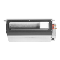
Do you have a question about the Hitachi RPI-0.8FSN4E and is the answer not in the manual?
Details on model classification, combinations, and identification of outdoor/indoor units.
Explanation of safety symbols and additional safety guidelines for operation and installation.
Identification of external and internal parts for the RAS-8FSXN1E outdoor unit.
Identification of external and internal parts for the RAS-(10/12)FSXN1E outdoor unit.
Identification of external and internal parts for the RAS-(14/16)FSXN1E outdoor unit.
Identification of external and internal parts for the RAS-(5/6)FSXNH(E) outdoor unit.
Identification of external and internal parts for the RAS-(8-12)FSXNH(E) outdoor unit.
Diagram illustrating the refrigerant flow and components for the RAS-(8-12)FSXN1E unit.
Diagram illustrating the refrigerant flow and components for the RAS-(14/16)FSXN1E unit.
Diagram illustrating the refrigerant flow and components for the RAS-(5/6)FSXNH(E) unit.
Diagram illustrating the refrigerant flow and components for the RAS-(8-12)FSXNH(E) unit.
Safe practices for transporting outdoor units, including securing and protecting them.
Precautions for handling units with fork-lift trucks to prevent injuries and damage.
Correct procedures for lifting outdoor units using slings, ensuring stability and safety.
Guidelines for selecting an appropriate installation location for the outdoor unit.
Required clearance dimensions around the outdoor unit for installation and maintenance access.
Spacing requirements for units installed near walls in different configurations.
Instructions for preparing foundations and securely anchoring the outdoor unit.
Guidelines for selecting appropriate refrigerant pipe sizes, types, and connection methods.
Specific connection diagrams and pipe sizing tables for different system configurations.
Procedure for performing an air-tight test to ensure system integrity before refrigerant charging.
Steps for vacuum pumping the system to remove air and moisture before refrigerant charging.
Methods for calculating the necessary additional refrigerant based on piping length and unit capacity.
Procedures for charging the system with refrigerant, including safety precautions.
Automated system for verifying refrigerant levels and identifying potential issues.
Guidelines for condensation drainage and leak countermeasures, including kit installation.
Diagrams and instructions for connecting power supply circuits to outdoor and indoor units.
Detailed instructions for wiring the outdoor unit, including terminal board connections and cable management.
Guide to configuring DIP switches on the PCB1 for unit settings and operation modes.
Procedures for setting external inputs/outputs and operational functions via the control panel.
Essential pre-test checks for refrigerant pipes, wiring, and system components.
Step-by-step instructions for performing the system test run and verifying operation.
A comprehensive checklist for verifying system parameters and performance during the test run.
A list of common alarm codes, their potential causes, and troubleshooting guidance.
Details on safety devices and mechanisms that protect the compressor from operating faults.
| Brand | Hitachi |
|---|---|
| Model | RPI-0.8FSN4E |
| Category | Air Conditioner |
| Language | English |


 Loading...