This document is an Operation, Installation & Maintenance Manual for HITACHI Inverter-Driven Multi-Split System Heat Pump Air Conditioners, specifically for the Indoor Unit. The manual, identified as P01068Q and dated 2016.10, provides essential information for the safe and correct use, installation, and maintenance of these units.
Function Description:
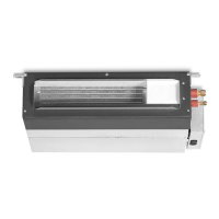
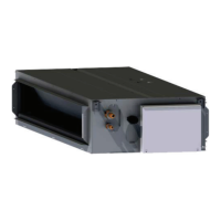
The HITACHI Inverter-Driven Multi-Split System Heat Pump Air Conditioners are designed for standard air conditioning, offering cooling, heating, dry, and fan operations. These units are part of a multi-split system, meaning a single outdoor unit can connect to multiple indoor units. The "Inverter-Driven" aspect indicates that the compressor speed can be varied, allowing for precise temperature control and energy efficiency. The "Heat Pump" functionality means the units can provide both cooling and heating by reversing the refrigerant flow. The indoor units covered by this manual are of the "In-The-Ceiling Type," suggesting they are designed for concealed installation within a ceiling space.
Important Technical Specifications:
The manual lists various models of the RPI-FSNQL(H) series, ranging from RPI-0.8FSNQL(H) to RPI-6.0FSNQL(H), indicating different capacities.
The nominal capacities (HP) for IN-THE-CEILING TYPE units are provided: 0.8, 1.0, 1.3, 1.5, 1.8, 2.0, 2.3, 2.5, 3.0, 3.3, 4.0, 5.0, and 6.0.
Operation ranges for temperature are specified:
- Cooling Operation: Indoor 32DB/23WB (Maximum), 21DB/15WB (Minimum)
- Heating Operation: Indoor 27DB (Maximum), 15DB (Minimum)
DB stands for Dry Bulb temperature, and WB stands for Wet Bulb temperature.
Electrical specifications for the power source are 220-240V~/50Hz or 220V~/60Hz.
The units use R410A refrigerant. The maximum allowable refrigerant quantity in the room where the indoor unit is installed is ≤0.3kg/m³.
Refrigerant piping connections vary by model:
- 0.8~1.5: Gas Piping φ12.7 (1/2), Liquid Piping φ6.35 (1/4)
- 1.8~2.0: Gas Piping φ15.88 (5/8), Liquid Piping φ6.35 (1/4)
- 2.3~3.3: Gas Piping φ15.88 (5/8), Liquid Piping φ9.53 (3/8)
- 4.0~6.0: Gas Piping φ19.05 (3/4), Liquid Piping φ9.53 (3/8)
Drain piping requires a polyvinyl chloride pipe with a 32mm outer diameter and must be performed with a DOWN-SLOPE pitch of 1/25 to 1/100.
Static pressure settings (Pa) are provided for different models:
- RPI-0.8~1.5FSNQL, RPI-0.8~1.5FSNQH: 30
- RPI-1.8~2.5FSNQL, RPI-1.8~2.5FSNQH: 60
- RPI-3.0~4.0FSNQL, RPI-3.0~4.0FSNQH: 50(*)/80
- RPI-5.0~6.0FSNQL, RPI-5.0~6.0FSNQH: 120()/90
(: Before Shipment)
Minimum wire sizes for the power source are also specified based on current (A) and comply with EN 60335-1. For example, for current ≤3A, 2.5mm² wire is required, and for current ≤63A, 25mm² wire is required.
Usage Features:
The system is controlled by a remote control switch, which is of the touching type. Users should press switches only with fingers. The temperature setting range is from 17°C to 30°C. Up to 16 indoor units can be controlled by one remote control switch.
The unit incorporates several automatic control features:
- Three Minute Guard (Enforced Stoppage): The compressor remains off for at least 3 minutes once it has stopped.
- Three Minute Guard (Enforced Start): The cooling operation or heating operation remains off and does not start until after 3 minutes has elapsed.
- Oil Return Operation: If an indoor unit is stopped for more than 2 hours, this function is operated during a few minutes to accumulate heat exchanger stoppage.
- Frost Prevention During Cooling Operation: Prevents frost formation on the indoor heat exchanger when the indoor unit is operated at low discharge air temperature.
- Hot Start During Heating Operation: To prevent cold air discharge, the fan speed is controlled from slow position to the low position, and then to the position according to the discharge air temperature.
- Slow Air Control During Defrosting Operation: When the outdoor unit is performing automatic defrosting, the indoor fan is stopped.
- Cooling of Indoor Unit: During heating operation, the indoor fan position is maintained at the minimum of 2 minutes to lower temperature of the inside unit.
- Automatic Defrosting Cycle: When defrosting operation is stopped, the outdoor unit is checked, and defrosting operation may be performed for the maximum of 10 minutes.
- Prevention of Overload Operation: During heating, if outdoor temperature is high, heating operation is stopped until the temperature lowers.
The system has a memory function for settings in case of brief power failures (up to 2 seconds), automatically restarting after approximately 3 minutes.
Maintenance Features:
The manual emphasizes the importance of regular checks and proper installation for safe operation.
- Troubleshooting: Provides guidance for common issues like "Not Cooling or Heating Well" and "No Operation," and identifies "Not Abnormal" sounds or smells. Users are advised to contact their contractor if trouble persists, providing unit model name, content of trouble, and alarm code.
- Electrical Wiring: Requires turning off the main power switch before any electrical wiring work or periodical checks. Screws must be tightened to specified torques (M3.5: 1.2 N-m, M5: 2.0~2.4 N-m).
- Safety Devices: An ELB (Electric Leakage Breaker) is recommended to prevent electric shock or fire.
- DIP Switches: The PCB in the indoor unit is equipped with rotary switches and dip switches for setting unit number, model code, capacity code, and refrigerant cycle number. These settings are crucial for proper operation and must be configured correctly during installation. Power must be turned OFF before setting DIP switches.
- Service Access: The installation requires a service access door (≥450mm) below the indoor unit for maintenance and removal.
- Air Filter: The air filter should be cleaned if clogged with dust.
- Drainage Check: After drain piping and electrical wiring, a check is required to ensure water flows smoothly by pouring 2 or 2.5 liters of water into the drain pan.
- Crankcase Heater: For long periods of shutdown, the main switch should be kept ON to energize the oil heater when the compressor is stopping.
The manual stresses the importance of reading and understanding it before using the air conditioners and keeping it for future reference. It also warns against improper disposal of the product and encourages recycling.

 Need help?
 General


 To Next Page
