Example of installation
For heat pump systems (2 pipes)
• For 3 units combination
Front side piping connection Downward piping connection
A
Gas pipe (eld-supplied)
D1
Liquid connection kit 1
G
Outdoor unit 2
B
Liquid pipe (eld-supplied)
D2
Liquid connection kit 2
H
Outdoor unit 3
C1
Gas connection kit 1
E
Accessory for connection of pipes (L-shaped)
I
Accessory for connection of pipes (Z-shaped)
C2
Gas connection kit 2
F
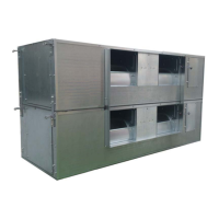
Outdoor unit 1
For heat recovery systems (3 pipes)
• For 3 units combination
Front side piping connection Downward piping connection
A
Gas pipe, low pressure (eld-supplied)
E1
Gas connection kit, high pressure 1
H
Outdoor unit 3
B
Gas pipe, high pressure (eld-supplied)
E2
Gas connection kit, high pressure 2
I
Outdoor unit 2
C
Liquid pipe (eld-supplied)
F1
Liquid connection kit 1
J
Outdoor unit 1
D1
Gas connection kit, low pressure 1
F2
Liquid connection kit 2
K
Accessory for connection of pipes
(Z-shaped)
D2
Gas connection kit, low pressure 2
G
Accessory for connection of pipes (L-shaped)
N
Accessory for connection of pipes
DANGER
• Check that the gas and liquid stop valves are fully closed.
• Check that there is no gas inside the pipe before remo-
ving the stop pipe. Otherwise, the pipe may explode
when heated with the blow torch.
Special care should be taken to ensure that the ame from the
blow torch does not fall on the body of the stop valve, on the com-
pressor and cover or on the insulation bushings; insert a metal
plate in front of the oil return pipe: see on chapter Gas stop valve.
Connect the indoor units to the outdoor units using copper pipes
specically for use with refrigerant. When laying the pipes make
sure that they do not directly rest on or touch walls or other parts
of the building (when the refrigerant is owing through the pipes,
this could cause strange noises).
Specic torques for the ared connections: see on chapter Flared
connection mounting.
While welding, apply a ow of nitrogen gas inside the pipe.
Fully insulate the refrigerant pipes.
CAUTION
Fit the pipe protection provided with the outdoor unit on comple-
tion of the installation work. Otherwise, the unit may be damaged
by the entrance of snow, water or rodents
NOTE
For heat pump systems (2 pipes)
Refer to the Factory-Supplied Accessories for the details of the
accessory pipes (B) and (C).
Ensure that the closing pipes of the high/low and low pressure
gas stop valves (2 parts) are removed rstly.
For heat recovery systems (3 pipes)
Refer to the Factory-Supplied Accessories for the details of the
accessory pipes (A), (B) and (C).
Ensure that the closing pipes of the high/low and low pressure
gas stop valves (1 parts) are removed rstly.
42
PMML0294A rev.2 - 07/2014
Piping work and refrigerant charge
PMML0294A_rev.2_02-2014.indb 42 14/07/2014 12:28:28
 Loading...