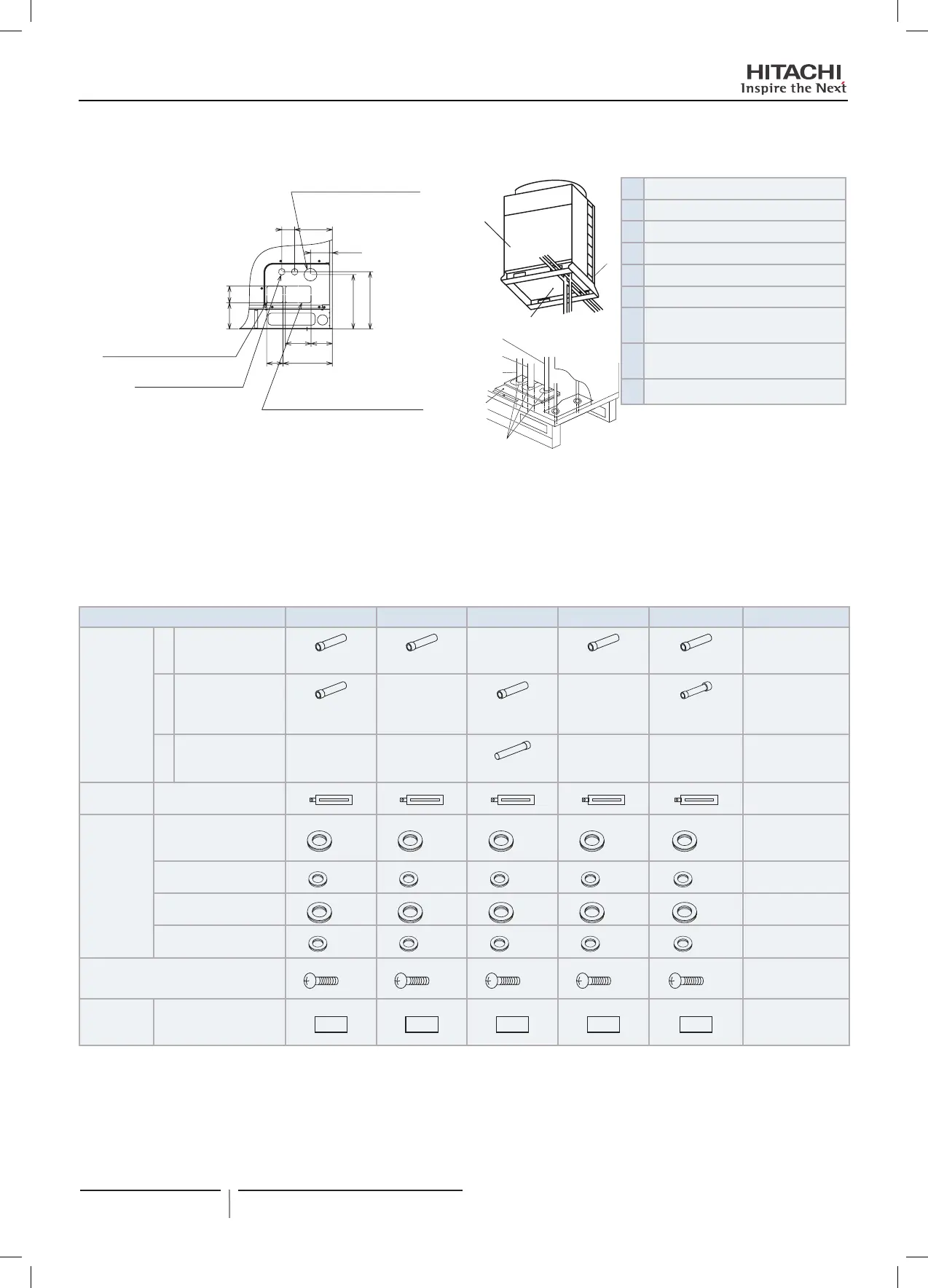
Connection position of outdoor unit pipes
85
82 250
130 108
132
110
19065
289
275
Power source cable outlet
(∅65 knockout hole)
Refrigerant piping outlet
(Low pressure gas)
Refrigerant piping outlet
(High/low pressure gas, liquid)
(Knockout square hole)
2 control cable outlets
(∅33 knockout hole)
(knockout square hole)
D
B
C
E
F
G
H
I
A
Front
B
Rear
C
Lower side
D
Base
E
Liquid pipe
F
Gas pipe (high pressure)
G
Gas pipe (low pressure) (only for heat
recovery systems, with CH units)
H
Cover of refrigerant gas and liquid
pipes
I
Cover insulation
Fit and secure refrigerant pipes correctly to prevent vibrations and strain on the stop valves.
The pipes may be tted in three directions (front, rear or inferior) from the base of the unit.
Remove the cover of the gas and liquid pipes -H- and connect using the accessories factory-supplied with the unit: see on chapter
Accessories factory-supplied with the unit.
Fit the cover on the pipes and completely seal around them and the cover to prevent the entrance of water, rodents and dirt.
Accessories factory-supplied with FSXN1E units
Accessory 8HP 10HP 12HP 14HP 16HP Remarks
Accessory
pipe
(A)
Connection for
refrigerant gas
(high/low) pipe
-
Only for heat
recovery system
∅22.2→∅15.88 ∅22.2→∅19.05 ∅25.4→∅22.2 ∅25.4→∅22.2
(B)
Connection for
refrigerant gas
(high/low) pipe
- -
* Low for heat
recovery system
* High/Low for
heat pump system
∅22.2→∅19.05 ∅22.2→∅25.4
∅25.4→∅28.58
(C)
Connection for
refrigerant liquid
pipe
- - - -
∅9.52→∅12.7
Cord clamp
For xing power source
cable
Rubber
bush
For power source cable
outlet (bottom base,
feet)
×2 ×2 ×2 ×2 ×2
∅58
For power source cable
outlet (piping cover)
×2 ×2 ×2 ×2 ×2
∅32
For transition wire outlet
(bottom base, feet)
×1 ×1 ×1 ×1 ×1
∅70
For transition wire outlet
(piping cover)
×2 ×2 ×2 ×2 ×2
∅38
Screw
(1 for xing cord clamp, 2 for spare)
×3 ×3 ×3 ×3 ×3
Combination
unit model
label
For identifying
combination unit model
22
PMML0294A rev.2 - 07/2014
Piping work and refrigerant charge
PMML0294A_rev.2_02-2014.indb 22 14/07/2014 12:28:12
 Loading...


