Do you have a question about the Hitachi SDT-7670 and is the answer not in the manual?
Always use genuine Hitachi replacement parts, especially critical power circuit parts.
Ensure the unit is completely safe to operate without danger of electrical shock after repair.
Details on semiconductor types, power supply, consumption, dimensions, and weight.
Specifications for speaker output, frequency response, S/N ratio, and tone control.
Specifications for tuner circuit system, tuning range, and sensitivity.
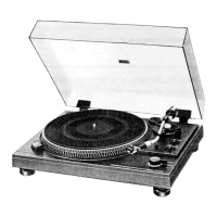
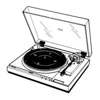
Specifications for the record player system, turntable, speed, motor, and cartridge.
Specifications for tape deck: tape type, speed, recording system, and frequency response.
Procedure for removing the cassette lid by moving it and lifting the tape counter side.
How to release the top panel lock using a screwdriver between the cassette tray and the panel.
Apply oil to rotating points and grease to sliding points, avoiding excessive lubrication.
List of parts requiring lubrication every 1000 hours or annually under normal use.
Step-by-step adjustments for tape deck: motor speed, head azimuth, VU meter, bias current, sensitivity.
Procedure for adjusting DNL (Dynamic Noise Limiter) input and output.
Adjustments for FM RF, FM Discriminator, FM Tracking, AM IF, SW RF, MW RF, and LW RF.
Procedures for adjusting FM multiplex and FM separation.
How to adjust the stylus pressure weight for the cartridge.
Procedure to adjust the motor pulley height for correct belt shifting.
How to adjust the pick-up arm height for proper record clearance.
Checking and adjusting the timing for auto return and power switch function.
Diagrams for RF, IF, Multiplex, and DNL sections of the circuit board.
Diagram showing the Band Switch assembly and connections.
Diagram showing the Function Switch assembly and connections.
Diagram showing the Pre-Tuned Control assembly and connections.
Diagram showing the Pre-Tuned Select assembly and connections.
Wiring diagram for the AF/Power section, including IC501A,B.
Wiring diagram for the headphone jacks (DIN and US-pin).
Wiring diagram for the DC motor.
Wiring diagram for the power transformer.
Wiring diagram for the power switch.
Layout of the control circuit board.
Layout of the jack circuit board.
Layout of the tape deck circuit board.
List of replacement capacitors with part numbers and descriptions.
List of replacement semiconductors (diodes, transistors, ICs, LEDs, FETs).
List of miscellaneous replacement parts like connectors, switches, and lamps.
List of parts specific to the record player section.
List of parts specific to the tape deck section.
Exploded diagram showing the upper and lower chassis assembly.
Layout of components and connections for the AF/Power section.
Layout of components and connections for the headphone jacks.
Layout of components and connections for the tuner section.
Layout of components and connections for the tape deck section.
Layouts of various switch assemblies and their components.
List of parts for the tuner chassis assembly.
List of miscellaneous parts for the tuner section.
Diagram illustrating the correct packing procedure for the device.
Description of functional blocks within the overall system block diagram.
Important notes and explanations related to the block diagram.
Wiring details for the 2 Meters, Stereo Indicator, 3 LEDs, and 5 Meters sections.
Wiring details for the AF/Power section and various indicators.
| Motor | DC Servo Motor |
|---|---|
| Overhang | 15 mm |
| Dimensions | 550 x 165 x 384 mm |
| Weight | 10 kg |
| Speeds | 33 1/3, 45, 78 RPM |
| Output Voltage | 2.5 mV |
| Platter | Aluminum die-cast |
| Cartridge Weight Range | 4-10 g |
| Cartridge | Moving Magnet |
| Frequency Response | 20 Hz to 20 kHz |
| Tonearm | Static balance type |
| Tonearm Type | Static balance type |