Do you have a question about the Hitachi TRK-8190E and is the answer not in the manual?
Details general, tuner, and tape recorder specifications for the unit.
Precautions for safe servicing and operation of the equipment.
Procedures for removing the head cover, cassette lid, and rear case.
Step-by-step guide for placing the dial cord correctly.
Guides for lubrication points, schedule, and mechanical part inspections.
Calibration procedures for FM, AM, SW, and MW/LW frequency bands.
Calibrating tape speed, azimuth, playback, recording, and Dolby NR.
Adjusting microswitch timing and DRPS operation level.
Detailed circuit schematics for tuner and tape recorder sections.
Visual layouts of various tuner, switch, DRPS, and power circuit boards.
Overall wiring and system block diagrams for unit connectivity.
Comprehensive list of replacement components, including semiconductors and resistors.
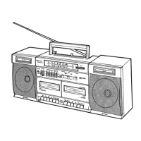
Diagrams showing disassembled cassette deck and cabinet components.
| Country | Japan |
|---|---|
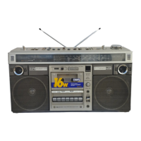
| Model | TRK-8190E |
| Type | Stereo System |
| Loudspeaker | 2 Loudspeakers |
| Radio | AM/FM |
| Manufacturer / Brand | Hitachi, Ltd. |
| Material | Plastic |
| Notes | Portable stereo system with radio and cassette |
| Cassette Deck | Yes |
| Inputs | Auxiliary |
| Outputs | Headphones |
| Power Source | AC, DC, or batteries |