Do you have a question about the Hitachi VM-7380E and is the answer not in the manual?
Detailed specifications for the video camera and its components.
Comparison of the current model with previous versions.
Comparison of main control integrated circuits.
Special tools and tapes required for adjustment procedures.
Diagrams for disassembly, reinstallation, and adjustment procedures.
List of abbreviations used throughout the service manual.
Identification of leadless (chip) components.
An excerpt from the user's instruction manual.
Procedures for disassembling cases and circuit boards.
Disassembly of lens hood, cassette lid, EVF holder, and EVF block.
Disassembly of AV jack cover and power switch knob.
Disassembly of camera block, tripod mount, VCR block, and right case.
Disassembly of handle, zoom switch, and hand strap.
Disassembly of SWS circuit board and tape transport mechanism.
Disassembly of CON circuit board, hood holder, lens block, CCD sensor, SPC board.
List of electrical components and their part numbers.
Internal wiring diagrams for various sections of the device.
Adjustments specific to the camera section of the device.
Identification of circuit board locations within the camera section.
List of test equipment required for camera section adjustments.
Conditions to meet before performing camera section adjustments.
Preset positions for switches and controls during adjustment.
Reference charts for performing camera section adjustments.
How to connect equipment for camera section adjustments.
Adjustments required after replacing major camera section components.
Step-by-step procedures for performing adjustments.
Procedure for starting the adjustment program using MAP.
Procedure for initial model setting during adjustment.
Procedure for adjusting electric volume settings.
Procedure for performing digital adjustments.
Procedure for adjusting the autofocus system.
Procedure for adjusting spot noise levels.
Procedure for adjusting the electronic viewfinder (EVF).
Procedure for adjusting CDS offset levels.
Procedure for adjusting CDS sampling pulse.
Procedure for adjusting the matrix settings.
Procedure for adjusting white balance.
Procedure for adjusting chroma gain.
Procedure for adjusting the autofocus system.
Procedure for adjusting the autofocus noise level.
Procedure for adjusting auto iris control.
Procedure for adjusting the knee level.
Information on leadless capacitors, including value and numbering.
Information on leadless resistors, including value and numbering.
Information on leadless jumpers.
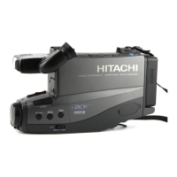
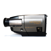
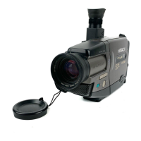
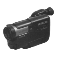
Overview of the camcorder's controls and their functions.
Exploded view of the first cabinet section.
Exploded view of the second cabinet section.
Exploded view of the chassis from the top.
Exploded view of the chassis from the bottom.
Exploded view of the electronic viewfinder (EVF) section.
Exploded view of the camera section.
Exploded view of available accessories.
Information on using battery and AC adapter/charger power sources.
Procedure for charging the camcorder battery pack.
Instructions for setting the date and time on the camcorder.
Troubleshooting guide for common issues and symptoms.
Procedures for maintaining the camcorder's optimal performance.
Instructions for cleaning the inside of the electronic viewfinder.
Disassembly of the electronic viewfinder (EVF) block components.
Disassembly of EVF holder, cable guide, and cable holder.
Disassembly of light cover, EVF top case, neck block, mic unit, light terminal, EVF board, bottom case.
Disassembly of eye cup, neck cases, mirror, EVF lens, CRT frame, and CRT.
Procedure for adjusting zoom and focus tracking.
Procedure for adjusting the autofocus noise level.
Procedure to adjust deflection yoke position in EVF.
Procedure for adjusting EVF centering.
Procedure for adjusting EVF vertical size.
Procedure for adjusting EVF brightness.
Procedure for adjusting EVF focus.
Adjustments specific to the VCR section of the device.
Identification of circuit board locations within the VCR section.
List of test equipment required for VCR section adjustments.
Conditions to meet before performing VCR section adjustments.
Preset positions for switches and controls during VCR adjustment.
How to connect equipment for VCR section adjustments.
Conditions for resetting VCR section components.
Step-by-step procedures for VCR section adjustments.
Procedure for adjusting the head switching point.
Procedure for adjusting the X-value for compatibility.
Error messages related to camera electric values and digital adjustments.
Error messages related to autofocus adjustment procedures.
Error messages related to spot noise adjustment.
Flowchart for troubleshooting autofocus operation issues.
Troubleshooting steps for no focus lens operation.
Troubleshooting steps for no zoom operation.
Troubleshooting steps for no autofocus operation.
Troubleshooting steps for focus issues when zoomed.
Exploded view of the first cabinet section.
Exploded view of the second cabinet section.
Exploded view of the chassis from the top.
Exploded view of the chassis from the bottom.
Exploded view of the electronic viewfinder (EVF) section.
Exploded view of the camera section.
Exploded view of available accessories.
List of mechanical parts with part numbers and descriptions.
Disassembly of the electronic viewfinder (EVF) block components.
Disassembly of EVF holder, cable guide, and cable holder.
Disassembly of light cover, EVF top case, neck block, mic unit, light terminal, EVF board, bottom case.
Disassembly of eye cup, neck cases, mirror, EVF lens, CRT frame, and CRT.
Procedure for adjusting zoom and focus tracking.
Procedure for adjusting the autofocus noise level.
Procedure to adjust deflection yoke position in EVF.
Procedure for adjusting EVF centering.
Procedure for adjusting EVF vertical size.
Procedure for adjusting EVF brightness.
Procedure for adjusting EVF focus.
Adjustments specific to the VCR section of the device.
Identification of circuit board locations within the VCR section.
List of test equipment required for VCR section adjustments.
Conditions to meet before performing VCR section adjustments.
Preset positions for switches and controls during VCR adjustment.
How to connect equipment for VCR section adjustments.
Conditions for resetting VCR section components.
Step-by-step procedures for VCR section adjustments.
Procedure for adjusting the head switching point.
Procedure for adjusting the X-value for compatibility.
Error messages related to camera electric values and digital adjustments.
Error messages related to autofocus adjustment procedures.
Error messages related to spot noise adjustment.
Flowchart for troubleshooting autofocus operation issues.
Troubleshooting steps for no focus lens operation.
Troubleshooting steps for no zoom operation.
Troubleshooting steps for no autofocus operation.
Troubleshooting steps for focus issues when zoomed.
| Camcorder Media Type | VHS-C |
|---|---|
| Optical Zoom | 8x |
| Digital Zoom | 32x |
| Image Sensor | CCD |
| Display Type | LCD |
| Type | Camcorder |
| Recording Format | VHS-C |
| Viewfinder | electronic |
| Focus | Auto |