Do you have a question about the Hitachi VM-E330E and is the answer not in the manual?
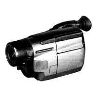
Details the technical specifications of the video camera/recorder models.
Compares features across different camera models.
Instructions for using the provided extension cable with the device.
A list of abbreviations used throughout the service manual.
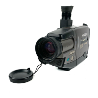
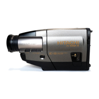
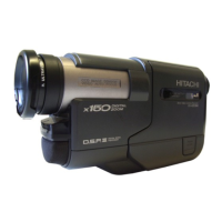
Identifies key components within the device for easier reference.
Outlines procedures for maintaining and inspecting the equipment.
Guides on manually setting the eject state for tape mechanisms.
Procedures for removing cases and the mechanism block.
A chart showing the hierarchical order of parts for removal.
Detailed procedures for removing specific components like cassette lid and lens ring.
Details on connecting test equipment for circuit adjustments.
Procedures for adjusting camera section circuitry.
Detailed steps for adjusting autofocus settings.
Procedures for adjusting the Electronic Viewfinder (EVF).
Procedures for adjusting the LCD display.
Procedures for adjusting VCR section circuitry.
Procedures for adjusting system control and servo circuits.
Procedures for adjusting luminance and chroma circuits.
Exploded views of the camera cabinet for different models.
Exploded view illustrating the internal chassis components.
Exploded view of the camera block assembly.
Exploded views of the EVF and LCD display components.
Exploded view of optional accessories for the device.
Comprehensive list of mechanical replacement parts and their numbers.
Comprehensive list of electrical replacement parts and their numbers.
Diagram showing internal wiring connections of the device.
Schematic diagram for the Sensor/Gyro (SE) section.
Schematic diagram for the Camera Process (VCA) section.
Schematic diagram for the System Control (VCA) section.
Schematic diagram for the Servo (VCA) section.
Visual representations of integrated circuit block functions.
Layouts of various circuit boards.
Block diagrams detailing the audio processing sections.
Block diagram showing the video processing sections.
Block diagram illustrating the power supply and distribution.
Pin function details for the digital microprocessor IC.
Pin function details for the system I/O control microprocessor.
An overview of the self-diagnostic capabilities and coverage.
Detailed information on self-diagnostic functions and their applications.
Procedures and results for mechanical block self-diagnosis.
Steps to disassemble the TH mechanism components.
Procedures for adjusting mechanism components like guide rollers.
Details the external buttons and switches on the camera body.
Explains LCD monitor operation, brightness, and viewing angles.
Lists the functions and operations of the remote control.
Step-by-step guide for charging the camera's battery.
Instructions for setting the device's date and time parameters.
Guides for diagnosing and resolving autofocus operational issues.
Troubleshooting steps for when zoom operation fails.
Troubleshooting steps for focus issues when the device is zoomed.
Exploded view and parts list for the AC adapter/charger.