Do you have a question about the Hitachi YUTAKI M and is the answer not in the manual?
Explains symbols used to indicate hazardous situations for safety and physical well-being.
Provides crucial safety instructions regarding electrical components, fire, and proper handling of the appliance.
Specifies required clearance around the remote control box for accessibility and servicing.
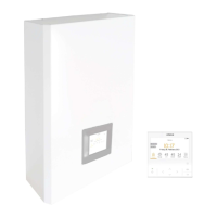
Identifies and lists all components within the remote control box assembly.
Details the procedure and dimensions for securely mounting the remote control box to a wall.
Explains the role of the remote control box as an extension of the hydraulic control system.
Describes how to activate and utilize the mirror function for system control.
Explains the system's operation when the mirror function is active, detailing master-slave roles.
Details the wiring procedures and connection points for the remote control box.
Explains how to connect the unit controller (PC-ARFH2E) to the remote control box PCB3.
Provides critical safety guidelines for electrical connections, power supply, and wiring.
Specifies required wire sizes and protection devices like CB and ELB for safe operation.
Outlines wiring procedures for optional accessories and their terminal board connections.
Details specific connections that must remain on the YUTAKI M unit's PCB2.
Shows the physical layout of DIP switches and rotary switches on PCB3 for configuration.
Explains the purpose and settings of various DIP switches (DSW1-DSW4) for system configuration.
Configures settings for outdoor unit sensors, allowing selection of preferred sensors for different circuits.
Configures operating mode (Remote/Local) and system mode (Heat/Cool) using rotary switches.
Describes the function and meaning of the various LEDs on the unit for status indication.
| Brand | Hitachi |
|---|---|
| Model | YUTAKI M |
| Category | Control Systems |
| Language | English |