EasyManua.ls Logo

Hitachi YUTAKI M RASM-6NE User Manual

Hitachi YUTAKI M RASM-6NE
194 pages
To Next Page IconTo Next Page
Page #1 background imageLoading...
Page #1 background image
YUTAKI SERIES

Table of Contents

Questions and Answers:

Hitachi YUTAKI M RASM-6NE Specifications

General IconGeneral
ModelRASM-6NE
Cooling Capacity6.0 kW
Seasonal Energy Efficiency Ratio (SEER)6.1
RefrigerantR410A
Heating Capacity7.0 kW
TypeSplit System Air Conditioner

Summary

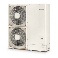
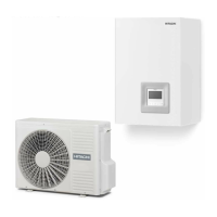
1.3 PRODUCT GUIDE

1.3.1 Classification of the units

Describes the classification of split and monobloc units based on model codes.

GENERAL SAFETY NOTES

2.1 ADDITIONAL INFORMATION ABOUT SAFETY

Provides detailed DANGER and CAUTION information for safe operation.

2.2 IMPORTANT NOTICE

Important instructions regarding manual reading, specifications, and usage.

GENERAL DATA

3.1 CAPACITY TABLES

Provides nominal capacity and performance data for YUTAKI S units.

3.2 ERP PERFORMANCE DATA

Details Energy-related Product (ERP) performance data for space heaters.

3.2.2 General ERP data for space heaters

Specific ERP data for YUTAKI S space heaters under average climate conditions.

3.2.2.2 ERP data - YUTAKI S COMBI

Specific ERP data for YUTAKI S COMBI units under average climate conditions.

WORKING RANGE

4.2 TEMPERATURE WORKING RANGE

Illustrates temperature working ranges for space heating and DHW.

4.2.1 Space heating

Shows temperature ranges for space heating for YUTAKI M and S80.

4.2.2 DHW

Shows temperature ranges for DHW for YUTAKI (S/S COMBI), M, and S80.

REFRIGERANT CYCLE AND HYDRAULIC CIRCUIT

5.1 REFRIGERANT CYCLE AND HYDRAULIC CIRCUIT FOR SPLIT SYSTEM

Illustrates refrigerant and hydraulic circuits for split systems.

5.2 REFRIGERANT CYCLE AND HYDRAULIC CIRCUIT FOR MONOBLOC SYSTEM - YUTAKI M

Illustrates refrigerant and hydraulic circuits for the monobloc YUTAKI M system.

REFRIGERANT AND WATER PIPING

6.1.2 Precautions in the event of gas refrigerant leaks

Critical safety precautions for refrigerant leakage scenarios.

ELECTRICAL AND CONTROL SETTINGS

7.2 ELECTRICAL CONNECTION

Details on power supply requirements and wiring.

7.2.1 Wiring size

Specifies wire sizes for power supply and communication cables.

7.2.2 Minimum requirements of the protection devices

Minimum requirements for Earth Leakage Breakers (ELB) and Circuit Breakers (CB).

UNIT CONTROLLER

8.5 WIZARD START-UP CONFIGURATION

8.5.1 Configuration Assistant

Provides a step-by-step guide for configuring the system.

8.6.2 System Configuration

8.6.4 Commisioning

TROUBLESHOOTING

9.1 Alarms for Indoor units

Lists indoor unit alarms, their codes, details, and main factors.

9.2 Alarms for Outdoor units

Lists outdoor unit alarms, their codes, details, and main factors.

9.3 Alarms for LCD

Lists alarms indicated on the LCD screen.

MAINTENANCE

10.1 MAINTENANCE WORK

General guidelines for maintenance tasks.

10.1.1 General maintenance procedure for the outdoor unit

Detailed maintenance steps for the outdoor unit components.

10.1.2 General maintenance procedure for the indoor unit

Detailed maintenance steps for indoor unit components.

Related product manuals