Do you have a question about the Hitachi Zaxis 330 and is the answer not in the manual?
Information for experienced technicians on maintaining and repairing the machine.
List of other manuals to consult alongside this one for comprehensive information.
Details the three main portions of the service manual: operational principle, troubleshooting, and workshop.
Explains the format and meaning of page numbers within the manual.
Explains safety symbols and signal words used to alert readers to potential hazards.
Details the SI units used in the manual and provides conversion factors to other systems.
Explains safety symbols, signal words, and their meanings for hazard awareness.
Covers safe operation, seat adjustment, seat belts, and hazard avoidance.
Details safe maintenance practices, tool usage, and workplace safety.
Covers fire prevention, handling fluids, hazardous materials, and emergency procedures.
Essential precautions and procedures for safely disassembling and assembling machine components.
Specifies tightening torque values and charts for various fasteners and components.
Provides guidelines and procedures related to painting machine parts and surfaces.
Covers the structure, components, and maintenance of the machine's operator cab.
Details the counterweight assembly, its installation, and related maintenance.
Information on the main frame structure, its components, and inspection points.
Information on the hydraulic pump device, its operation, and maintenance.
Details the control valve assembly, its functions, and service procedures.
Covers the swing mechanism, including its components and maintenance requirements.
Information on pilot valves, their role in the hydraulic system, and servicing.
Details the pilot shut-off valve, its function, and maintenance procedures.
Information on shockless valves, their purpose, and related service.
Covers solenoid valves, their operation in control systems, and maintenance.
Details the swing bearing, its lubrication, inspection, and replacement.
Covers the travel drive motors, gearboxes, and related maintenance.
Information on the center joint, its seals, and service procedures.
Details the track tensioning system, adjuster, and maintenance.
Information on the front idler, its role, and maintenance.
Covers the track rollers (upper and lower), their inspection, and maintenance.
Information on the track assembly, pins, links, and maintenance.
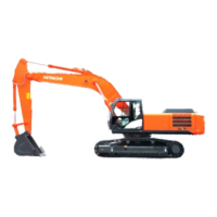
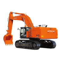
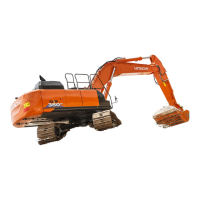
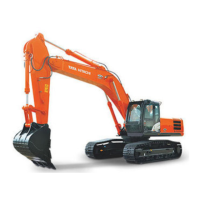
Covers the main front attachment components like boom, arm, and bucket.
Details the hydraulic cylinders for boom, arm, and bucket, including seals and maintenance.
| Brand | Hitachi |
|---|---|
| Model | Zaxis 330 |
| Category | Excavators |
| Language | English |