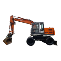
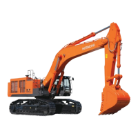
This document is a Workshop Manual for the Hitachi ZX series of hydraulic excavators, specifically models ZX870-5G, 870LC-5G, 870H-5G, 870LCH-5G, and 870LCR-5G. It is identified by Part No. WJBE-EN-00 and was printed in Japan in July 2012. The manual provides comprehensive information for the maintenance, repair, and troubleshooting of these heavy-duty construction machines.
The Workshop Manual is part of a larger service manual set, which also includes a Technical Manual (Operational Principle) (Vol. No. TOJBE-EN) and a Technical Manual (Troubleshooting) (Vol. No. TTJBE-EN). This indicates a structured approach to providing service information, with each volume focusing on a specific aspect of the machine's operation and upkeep.
The manual is organized into several key sections, each addressing different components and aspects of the excavator:
This foundational section covers essential procedures and guidelines applicable to all maintenance and repair activities.
- Group 1: Precautions for Disassembling and Assembling: This group emphasizes safety and best practices during machine disassembly and reassembly. It includes instructions for cleaning the machine, inspecting components, preparing tools and the work area, and handling disassembled parts. Key precautions include capping open ends of hoses and pipes, using identification tags, draining fluids, using matching marks for reassembly, and employing specified special tools. It also details precautions for assembling, such as cleaning all parts, preventing contamination, applying lubricants, replacing O-rings and seals, and ensuring no tools are left inside the machine. A specific subsection on "Precautions for Using Floating Seal" outlines procedures for inspecting and reusing floating seals, emphasizing the importance of correct installation to prevent oil leakage or damage. It advises checking for scuffing, scoring, corrosion, deformation, or uneven wear on seal rings and O-rings, and ensuring proper alignment during installation. Another critical part of this group is "Precautions for Using Nylon Sling," which provides detailed safety guidelines for lifting loads with nylon slings. It stresses the use of protectors on load corners, temperature limits for lifted loads (below 100 °C or 212 °F), avoidance of acid or alkali chemicals, and keeping slings dry. It also covers proper sling selection (same width and length for multiple slings), ensuring no gaps when lifting with eyeholes, avoiding twisted or bent slings, and proper storage. A "CAUTION" note highlights the severe personal injury risk associated with using damaged nylon slings and instructs users to visually inspect slings for damage and discard them if any is found or if they are older than 7 years.
- Group 2: Tightening Torque: This group provides crucial specifications for tightening bolts and nuts, ensuring proper assembly and preventing loosening or damage. It includes a "Specified Tightening Torque Chart" with values in N·m, kgf·m, and lbf·ft for various bolt diameters (M6 to M36) and different bolt grades (10.9, 8.8, and socket bolts). Important notes emphasize applying lubricant to bolts and nuts to reduce friction, a torque tolerance of ±10%, using bolts of correct length, and cleaning threads. It also illustrates tightening orders for multiple bolts (equally tighten upper and lower alternately, tighten diagonally, and tighten from center diagonally) to ensure even clamping force.
- Group 3: Painting: This group likely covers specifications for painting and touch-up procedures, including paint types and application guidelines.
- Group 4: Bleeding Air: This group details procedures for bleeding air from critical hydraulic and fuel systems, including the hydraulic oil tank, hydraulic system, fuel system, and radiator. Proper air bleeding is essential for the correct operation and longevity of these systems.
- Group 5: Pressure Release Procedure: This group outlines the steps for safely releasing pressure from the hydraulic circuit before performing any maintenance or repair work, a critical safety measure.
- Group 6: Preparation: This group covers general preparation steps before inspection and maintenance, ensuring the machine is ready for service.
Section 2: Maintenance Standard
This section establishes the benchmarks for evaluating component wear and performance.
- Group 1: Upperstructure: Standards for the main body of the excavator.
- Group 2: Undercarriage: Standards for the track system and related components.
- Group 3: Front Attachment: Standards for the boom, arm, bucket, and other attachments.
The "Maintenance Standard Terminology" defines "Standard" as the dimension for new parts or components adjusted to specification, with allowable errors indicated. "Allowable Limit" is defined as the point beyond which normal machine performance cannot be accomplished, repair or adjustment becomes difficult or impossible, and proper maintenance should be carried out before reaching this limit to ensure operational efficiency and manage maintenance expenses.
Section 3: Upperstructure
This section provides detailed information on the components located on the upper part of the excavator.
- Group 1: Cab: Maintenance and repair of the operator's cabin.
- Group 2: Counterweight: Information on the counterweight system.
- Group 3: Main Frame: Details on the structural integrity of the main frame.
- Group 4: Engine: Maintenance and repair procedures for the engine.
- Group 5: Radiator Assembly: Information on the cooling system.
- Group 6: Hydraulic Oil Tank: Maintenance of the hydraulic fluid reservoir.
- Group 7: Fuel Tank: Maintenance of the fuel storage system.
- Group 8: Pump Device: Details on the hydraulic pumps.
- Group 9: Control Valve: Maintenance of the main hydraulic control valve.
- Group 10: Swing Device: Information on the swing motor and gearbox.
- Group 11: Pilot Valve: Maintenance of the pilot control valves.
- Group 12: Solenoid Valve: Details on the electrical solenoid valves.
- Group 13: Signal Control Valve: Information on the signal control system.
- Group 14: Shockless Valve: Maintenance of the shockless valve.
- Group 15: Fan Valve: Details on the fan control valve.
- Group 16: Fan Motor: Maintenance of the cooling fan motor.
Section 4: Undercarriage
This section focuses on the components of the excavator's track system.
- Group 1: Swing Bearing: Maintenance of the large bearing that allows the upperstructure to rotate.
- Group 2: Travel Device: Details on the travel motors and final drives.
- Group 3: Center Joint: Maintenance of the rotary joint that allows hydraulic fluid to pass between the upperstructure and undercarriage.
- Group 4: Track Adjuster: Information on adjusting track tension.
- Group 5: Front Idler: Maintenance of the front idler wheel.
- Group 6: Upper and Lower Roller: Details on the track rollers.
- Group 7: Track: Maintenance and repair of the track links and shoes.
Section 5: Attachment
This section covers the working tools of the excavator.
- Group 1: Front Attachment: Maintenance of the boom, arm, and bucket structure.
- Group 2: Cylinder: Details on the hydraulic cylinders for the boom, arm, and bucket.
Section 6: Engine
This section, though listed, likely refers to more specific engine details or cross-references the engine manufacturer's manual, as a general "Engine" group is already present in Section 3.
Technical Manual (Operational Principle) (Vol. No. TOJBE-EN)
This companion manual provides a theoretical understanding of the excavator's systems.
- Section 1: General: Covers specifications, component layout, and component specifications.
- Section 2: System: Explains the controller, control system, hydraulic system, and electrical system.
- Section 3: Component Operation: Details the operation of the pump device, swing device, control valve, pilot valve, travel device, signal control valve, and other upperstructure and undercarriage components.
Technical Manual (Troubleshooting) (Vol. No. TTJBE-EN)
This companion manual is dedicated to diagnosing and resolving issues.
- Section 4: Operational Performance Test: Includes introduction, standards, engine test, excavator test, component test, and adjustment procedures.
- Section 5: Troubleshooting: Covers diagnosing procedures, monitor information, e-Service functions, component layout for troubleshooting, and specific troubleshooting guides (A and B), as well as air conditioner troubleshooting.
Overall, this Workshop Manual, along with its companion Technical Manuals, forms a comprehensive resource for the maintenance, repair, and operational understanding of the Hitachi ZX series hydraulic excavators. It emphasizes safety, systematic procedures, and adherence to specifications to ensure reliable operation and extended service life of the machinery. The detailed breakdown of components and systems, coupled with specific instructions for tasks like tightening, bleeding, and pressure release, makes it an indispensable tool for service technicians.

 Need help?
 General

 To Next Page