20 21
9 CHANNEL 2.4GHz AIRCRAFT COMPUTER RADIO SYSTEM 9 CHANNEL 2.4GHz AIRCRAFT COMPUTER RADIO SYSTEM
Telemetry System
Currently there are two direct feedback telemetry functions available in your Hitec 2.4 system. Plans are to have many more
devices available in the future. Check the Hitec web site at www.hitecrcd.com for more up-to-date information.
I. Low Battery Warning
The 2.4 system will automatically recognize the receiver battery voltage among 4 and 5 cell NiMH or Nicad packs and 2S Li-Po/Io/Fe
batteries packs.
- When battery level is high (4 cell > 4.5V, 5 cell > 5.6V): The red module LED glows constantly.
- When battery level is low (4 cell < 4.5V, 5 cell < 5.6 V): blue LED glows constantly and the red LED will blink fast.
You will hear a continuous loud beep from the module as a low receiver battery warning. Upon hearing the alarm, we advise you to
land at once.
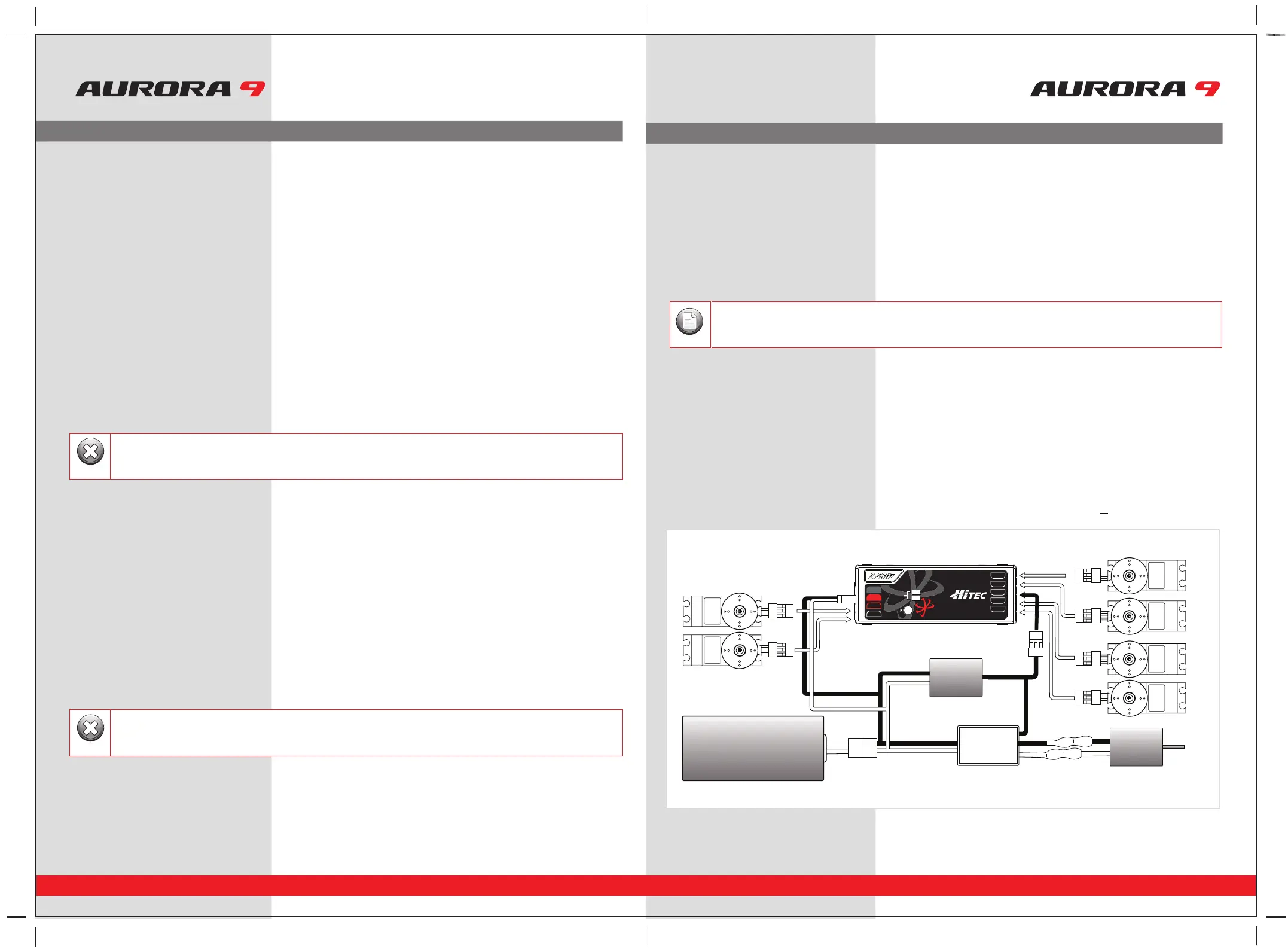
SPC (Supplementary Power Connection) System
Hitecs exclusive optional receiver power system allows you to directly power the receiver from the main motor power battery of
an electric powered aircraft. Up to 35 Volts can be fed directly into the receiver to power JUST THE RECEIVER FUNCTION. It will not
power the servos. Almost all servos will burn-up if more than 6 Volts are used over a short period of time.
Note; some Hitec servos are rated to be used at 7.4Volts. You will still need to supply power for your servos with a four or
five cell NiMH receiver battery, 2 cell Li-Po and regulator set-up, or a commercially available BEC. The SPC system was partially
created to be integrated into future Hitec telemetry system devices. Check the Hitec web site for more information on the availability
of telemetry systems in the future.
SPC Receiver Connection Diagram
Set-up and Use of the Hitec 2.4GHz System
FAIL-SAFE Setup
a. Switch on the transmitter, then the receiver, wait for the system to boot and you have control over the model.
b. Press and hold the receiver function button for 6 seconds, release the button. After 2 more seconds both red and blue
LEDs blink rapidly.
c. From the moment you release the button, the receiver will count 5 seconds during that time move all the transmitter sticks
and other controls to the desired FAIL-SAFE positions (e.g. motor idle, control surfaces neutral), and hold them there.
d. After 5 seconds the system will save the FAIL-SAFE position. Relax all the control sticks.
e. Turn off the receiver, then the transmitter.
f. Turn on the system to use it. FAIL-SAFE is now activated.
Testing the FAIL-SAFE Setting
a. Move the sticks to positions other than the FAIL-SAFE settings, and then switch off the transmitter. The servos should now
move to the FAIL-SAFE positions previously stored, after the HOLD period (1 sec.) has elapsed.
How to turn FAIL-SAFE Off and reactivate the Hold Mode
a. Switch on the transmitter, then the receiver. Wait for the system to boot and you have control over the model.
b. Press and hold the receiver function button for 6 seconds and release it. After 2 seconds the red and blue LEDs will blink rapidly.
c. Immediately press the button and release it.
d. FAIL-SAFE Mode is now deactivated and HOLD mode is activated.
e. Turn the transmitter off, then the receiver off.
f. Turn the system back on to use it.
Range Check Function
It is critical that before each flight session you perform a range check that confirms the signal between the receiver and transmitter is
appropriate. Unlike the FM/PPM or PCM signal radios, 2.4GHz systems use a fixed shorter, stubby transmitter antenna so the traditional
method of range checking your system by lowering the transmitter antenna will not work.
We instead use a power-down mode to reduce the transmitter signal strength. Once the power-down mode is activated it runs for about
90 seconds, shortening the effective range 100 feet (30 m). During this power-down mode that you should walk away from the secured
aircraft carrying the transmitter to a distance of approx. 30 meters, testing the effective range.
How to use Power-Down
a. Press the button on the module for 3 seconds, then both the blue and red LEDs will turn on with single beep sound. Release the
button. The 90-second countdown starts from the time the button released.
b. Walk away from the secured aircraft carrying the transmitter to a distance of approx. 100 feet (30 m), testing the effective range.
c. To exit the power-down mode before the 90 seconds, press the button again to escape.
Set-up and Use of the Hitec 2.4GHz System
- If FAIL-SAFE is deactivated, the FAIL-SAFE position settings are also deleted!
- The FAIL-SAFE settings should be checked every time before you run the engine/motor.
Warning
If you are unable to accomplish a successful range check of 90 feet, DO NOT ATTEMPT TO FLY.
Warning
BAT/CH7
CH6
DATA
SPC
LEDLED
LINKLINK
LED
LINK
CH1
CH2
CH3
CH4
CH5
OPTIMA OPTIMA 77OPTIMA 7
2.4GHz 7 Channel Aircraft Receiver2.4GHz 7 Channel Aircraft Receiver2.4GHz 7 Channel Aircraft Receiver
AFHSS
2.4GHz
Telemetric
ADAPTIVE
FREQUENCY HOPPING
SPREAD SPECTRUM
SERVOSERVO
SERVOSERVO
SERVO SERVO
Power Battery
Motor
BEC
ESC
The low battery voltage warning can be custom programmed with the HPP-22
Note