16 17
9 CHANNEL 2.4GHz AIRCRAFT COMPUTER RADIO SYSTEM 9 CHANNEL 2.4GHz AIRCRAFT COMPUTER RADIO SYSTEM
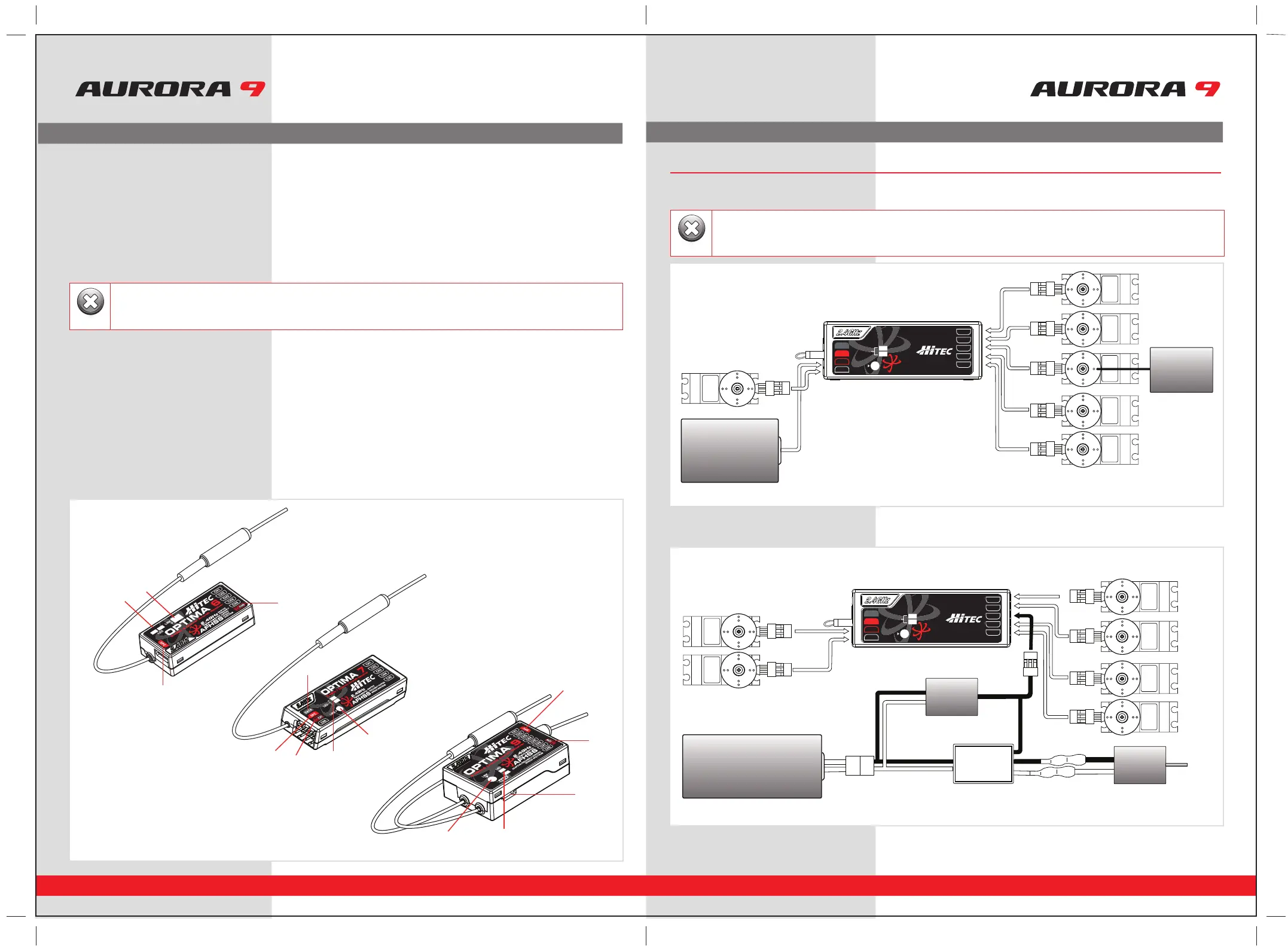
Optima Receiver Connection Diagrams
4. SPC Supplementary Power Connection
Power the Optima receiver function with up to a 35V. motor battery. Details about the SPC system can be found on page 21.
5. Channel Output and Battery Input Ports
The ports for battery power, servos, gyros and other accessories are located at each end of the streamlined Optima receivers.
6. Jumpers
The jumper is installed at the factory and is used when the receiver is powered by an electronic speed control,
a commercially available B.E.C. (battery eliminator circuit), dedicated 4.8 to 6V. NiMH battery pack, or *2S Li-Po/Io/Fe batteries.
The jumper is removed when the receiver is powered using the SPC feature as described in more detail on page 21.
Compatibility
The Optima series receivers are compatible with transmitters using the Hitec AFHSS 2.4GHz system Spectra 2.4GHz module or
dedicated non-module AFHSS Hitec transmitters in the future.
Normal / Scan Mode Selectable
Select between two operational signal types. See page 19 for details.
FAIL-SAFE Option
Servos and other accessories may be programmed with a FAIL-SAFE point in the event power to the receiver is interrupted.
See page 19 for details.
Onboard Receiver Battery Warnings
Know when your on-board battery is low with direct telemetry feedback to your transmitter. See page 21 for details.
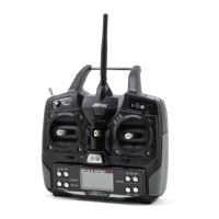
Hitec 2.4GHz System Set-up
Hitec 2.4GHz System Set-up
Warning
1. Function Button
2. Dual LED Status Indicator
3. Channel Output and Battery Input Ports
4. SPC (Supplementary Power Connection)
5. Telemetry Sensor and System Port
Electric powered aircraft with Electronic Speed Control
Use this method on electric planes using ESC’s providing power to the receiver and servo functions.
Optional BEC shown in diagram is used if the servo power requirements exceed that which the ESC provides.
SERVOSERVO
SERVOSERVO
SERVO SERVO
Power Battery
Motor
BEC
ESC
Glow, gas or electric powered aircraft using a separate receiver battery supply.
Follow this connection diagram when using a dedicated 4.8 to 6V. NiMH battery pack, or *2S Li-Po/Io/Fe batteries.
BAT/CH7
CH6
DATA
SPC
LEDLED
LINKLINK
LED
LINK
CH1
CH2
CH3
CH4
CH5
OPTIMA OPTIMA 77OPTIMA 7
2.4GHz 7 Channel Aircraft Receiver2.4GHz 7 Channel Aircraft Receiver2.4GHz 7 Channel Aircraft Receiver
AFHSS
2.4GHz
Telemetric
ADAPTIVE
FREQUENCY HOPPING
SPREAD SPECTRUM
BAT/CH7
CH6
DATA
SPC
LEDLED
LINKLINK
LED
LINK
CH1
CH2
CH3
CH4
CH5
OPTIMA OPTIMA 77OPTIMA 7
2.4GHz 7 Channel Aircraft Receiver2.4GHz 7 Channel Aircraft Receiver2.4GHz 7 Channel Aircraft Receiver
AFHSS
2.4GHz
Telemetric
ADAPTIVE
FREQUENCY HOPPING
SPREAD SPECTRUM
SERVOSERVO
SERVO
SERVO SERVO
Receiver
Battery
SERVO
Engine
5
4
3
3
2
1
1
1
2
2
3
4
4
5
*Verify your servos are rated for use with these higher voltage batteries or use a regulator.
Warning
*Verify your servos are rated for use with these higher voltage batteries or use a regulator.