14 15
9 CHANNEL 2.4GHz AIRCRAFT COMPUTER RADIO SYSTEM 9 CHANNEL 2.4GHz AIRCRAFT COMPUTER RADIO SYSTEM
The Aurora offers the option to use the SPECTRA PRO 72MHz module for 72MHz operation, or SPECTRA 2.4 AFHSS
module for 2.4GHz operations. Please read the following text that explains the installation and set-up process for
these two options.
SPECTRA PRO 72MHz
With the SPECTRA PRO frequency synthesizer module, you choose what 72MHz channel you want to use for any of the
thirty model memories in the Aurora.
SPECTRA PRO Compatibility
Receiver Compatibility
When used in the Aurora, the SPECTRA PRO will fly models using any brand of 72MHz FM PPM receiver, or the Hitec QPCM receiver.
Transmitter Capability
The SPECTRA PRO will work in the Aurora transmitter only! As of this writing, it is not compatible with any other current R/C product.
Installation of the SPECTRA PRO
a. To install the SPECTRA PRO module, make sure the power is OFF.
b. Fit the SPECTRA PRO into the module pocket in the back of the Aurora radio case.
c. Line-up the pins with the mating connector and gently plug it in until the module is properly seated in the radio case.
How to use the SPECTRA PRO
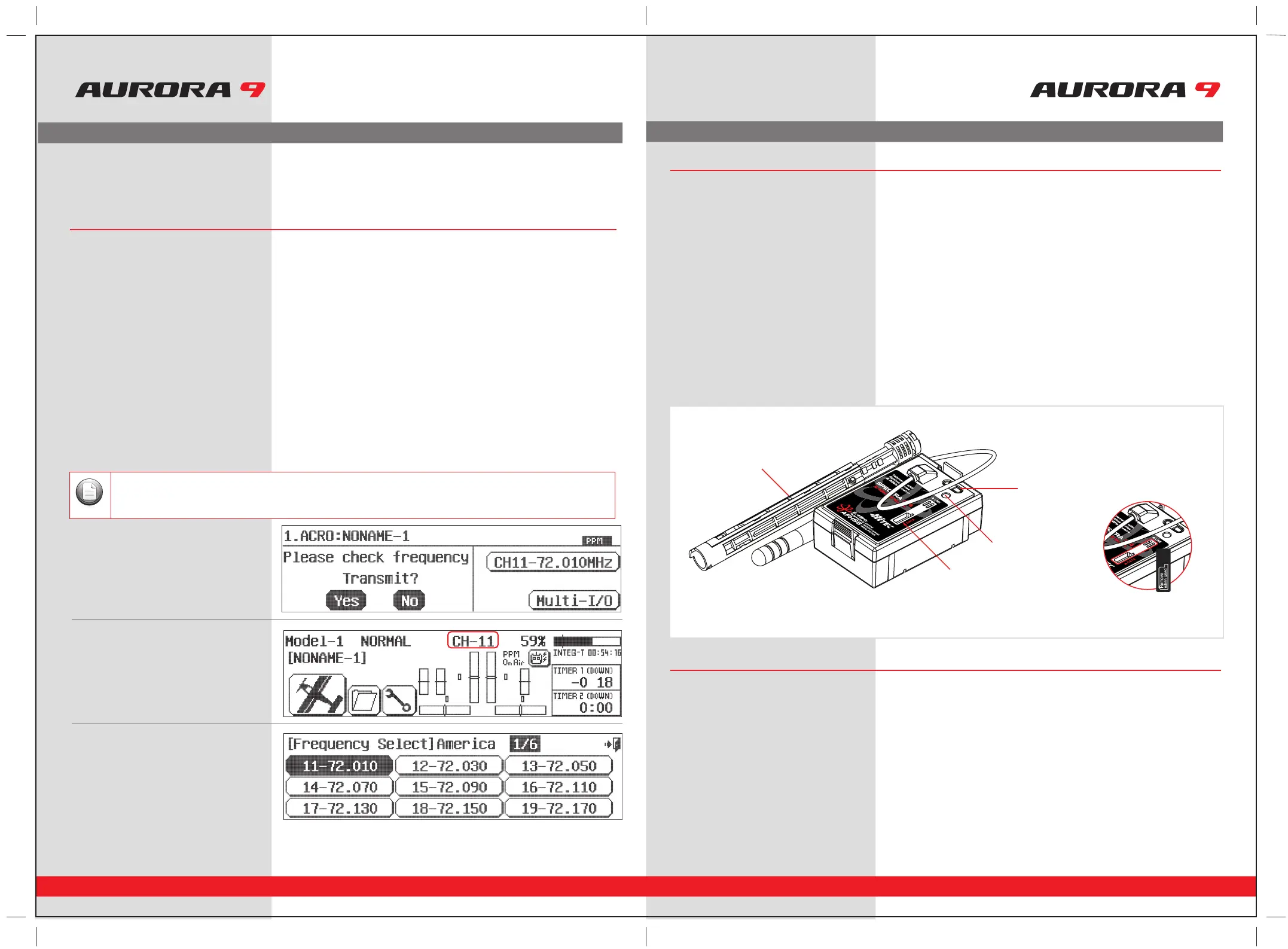
There are several ways to change a models frequency in the Aurora.
For detailed instructions on changing the channel, consult page 57, the System menu, Freq Sel function.
1. At the very first screen,
by pressing the channel icon.
2. At the home screen by pressing the
CH-XX icon.
3. In the System menu, Freq-Sel menu.
Signal Modulation Options
In all cases shown below, PPM or QPCM must be selected as the radios signal modulation.
Note
SPECTRA 2.4GHz Module Features
The following contains the complete instructions on how to use the Optima 2.4GHz series receivers and SPECTRA 2.4GHz
module set for a trouble free 2.4GHz signal. We encourage you to review this information before using these products.
Optima Series Receiver Features
As of this writing, there are three Optima 2.4GHz receivers that are compatible with the SPECTRA 2.4GHz module.
The Optima 6, Optima 7 and the Optima 9 channel products are loaded with a variety of functions that are sure to
deliver a satisfying R/C experience.
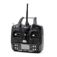
1. Dual Blue and Red Status indicator LED’s
Indicates the set-up process codes and use status.
2. Function Button
Used for Linking(ID -Setting) the module to a receiver, entering the power down mode for range checks and the Nomal / Scan
Mode set-up.
3. Sensor Data Output and System Upgrade Connector Port
A 3 pin servo plug connector port is featured on the 2.4GHz module. Using the HPP-22 PC interface accessory this port serves to
facilitate upgrading the devices software and downloading information from Optima 7 and 9 channel receiver if using optional
onboard sensor station.
4. Adjustable Antenna
The antenna is an adjustable two piece unit hardwired to the module.
1. Telemetry Sensor and System Port
A three pin servo plug connector port is featured on the Optima 7 and 9 ch. receivers. Using the HPP-22 PC interface accessory this port
serves to facilitate upgrading the devices software and interfacing the optional onboard sensor station.
2. Function Button
Used for Linking(ID-Setting) the receiver to a module, entering Fail-Safe / Hold mode setup function.
3. Dual LED Status Indicator
Indicates the set-up process codes and use status.
Hitec 2.4GHz System Set-up
3-1.
Sticker Seal
4. Antenna
2. Function Button
3. Sensor Data Output &
System Update Port
1. LED