10
LINE DIAMETER
DIAMETER OF GAS LINES
In the cooling operation suction line
hold gas refrigerant and in the heat
pump operation discharge line is also
gas line. Line diameter is selected in the
most unfavourable conditions. It is nec-
essary to check for both cases.
In the case of the layout shown on fig-
ure 2 the suction line velocity will pro-
duce the worse conditions and gas line
diameter selection is for suction line. It
is necessary to check also the discharge
line. The suction and discharge calcu-
lations are done in the same way using
graphs 1 and 2 where pressure are re-
ferred to 10 meters of equivalent length
for each diameter.
For larger or smaller equivalent lengths
pressure drop is obtained in the direct
proportion. The line total pressure drop
(horizontal plus vertical pipe runs) must
never be higher than 20 kPa.
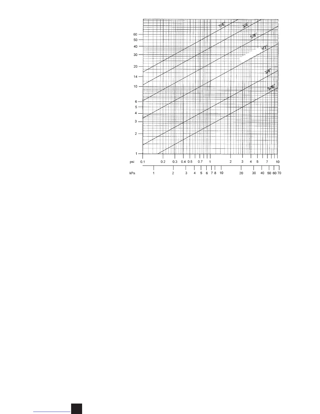
DIAMETER OF LIQUID LINES
To determine the liquid line diameter
use graph 3, the pressure drop in this
line should be below 68 kPa.
Nominal cooling capacity (kW) of one circuit
Pressure drop per 10 m. of equivalent length
Diameter
Graph 3 - Liquid line.
START UP
PRELIMINARY CHECK UP
It is very important to check the following points be-
fore first unit start up:
1. All the electrical connections are well tight.
2. Unit is level installed and has proper supporting
structure.
3. Air ducts have been not damaged during the instal-
lation.
4. Air filters are correctly mounted and are clean.
5. All panels are at their place and the screws tights.
6. Unit has easy maintenance and service access.
7. Openings and/or drain connections for rain and de-
frost (heat pumps) water evacuation are not blocked.
8. Check if there are no refrigerant leaks.
9. Electrical power source agrees with the unit name-
plate rating.
10. Check for proper fan rotation.
ATTENTION: The compressors are mounted on vibra-
tion isolators. Check if mounting bolts have been not
loosen or removed by mistake.
UNIT START UP
Start up must be performed by qualified and
trained service personnel.
ATTENTION, CRANKCASE HEATER: to avoid re-
frigerant condensation in the compressor(s) and refrig-
erant absorbtion in oil when not operating, compres-
sors are fitted with a crankcase heater. This electrical
resistance is connected on normally closed contacts
from the compressor(s) contactor(s), thus when main
power of the unit is live the heating is effective only
when the conpressor(s) is(are) not running.
Make sure that this heating element is under power
for at least 24 hours before the first start up of the com-
pressor (thermostat on "OFF" position).
At start up time a check list of all parameters must be
established. Consult, and eventually modify, this check
list when servicing the unit and for maintenance op-
erations.