13
REMOTE CONTROL OPERATION
CONTROL SYSTEM
The unit is controlled from a remote room thermostat.
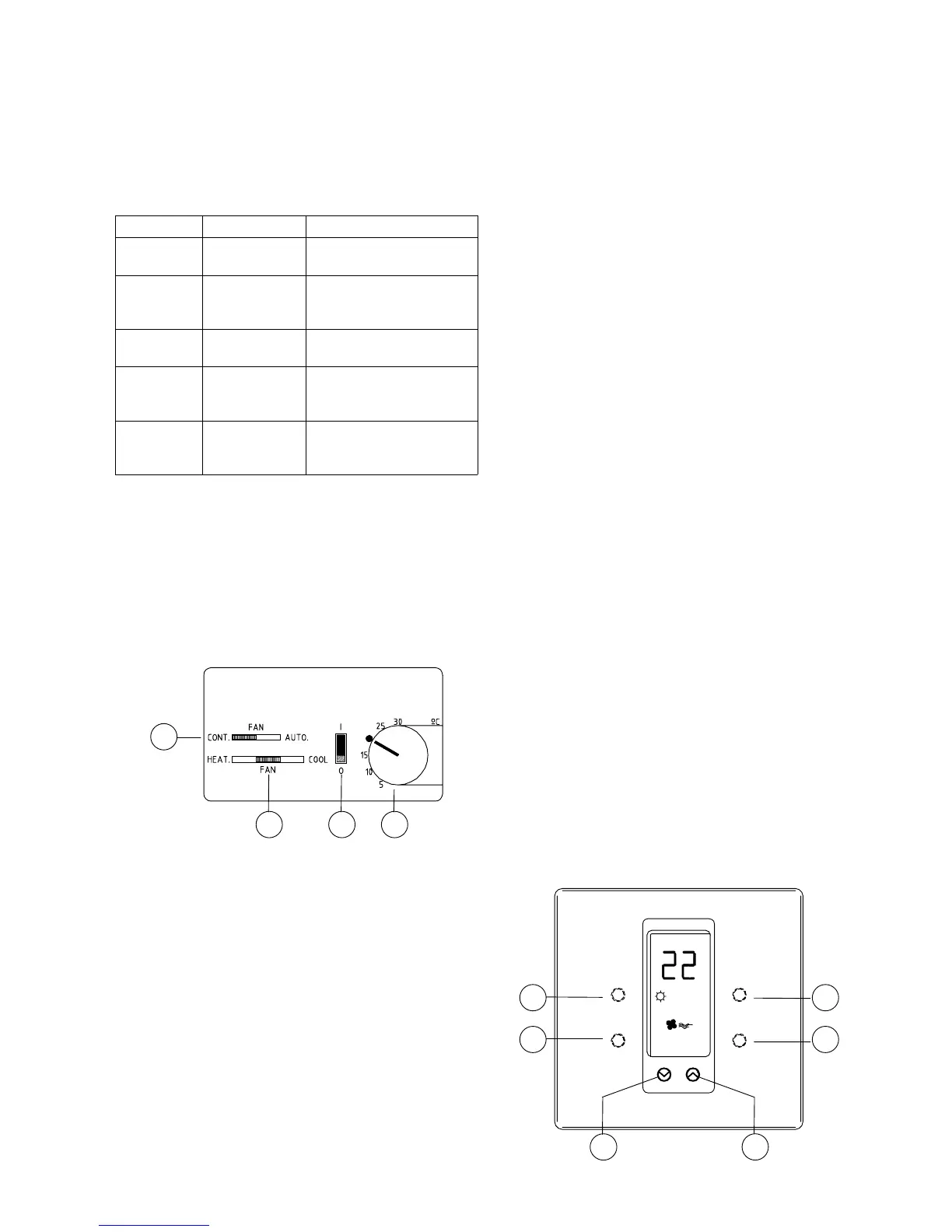
Type of thermostat is indicated in the following table:
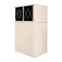
RTR 7007 and RTR 7035
CONTROL BUTTONS
c ON/OFF SWITCH
d TEMPERATURE SELECTOR
e FAN OPERATING MODE SELECTOR: fan oper-
ate only when system is operating in cooling or heat-
ing, or continuous fan operation.
f COOLING AND HEATING MODE SELECTOR:
thermostat is controlling room temperature when the
system is operating in cooling or heating mode.
USER'S SETTING POSSIBILITIES
STARTING UP THE SYSTEM - Displace the ON/OFF
selector c to position "I".
COOLING - Select "COOL" position with selector f.
Adjust required room temperature with knob d. If this
temperature is below the effective room temperature
the compressor will operate after a time delay.
HEATING - Select "HEAT." position with selector f.
Adjust required room temperature with knob d.
Cooling systems with auxiliary heater: If this tem-
perature is above the effective room temperature the
contactor will energize the heating element.
Heat pump systems: If this temperature is above the
effective room temperature the compressor will oper-
ate after a time delay. Auxiliary heater is controlled
by the outdoor thermostat.
FAN - Select fan operating mode with switch e: "AUTO"
(fan activated when the system is operating in cooling
or heating mode) or continuous "CONT." (not depend-
ant on system compressor operation).
SWITCHING DOWN THE SYSTEM - Displace the ON/
OFF selector c to position "0".
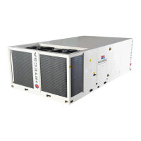
DSL-450, DSL-600 and DSL-700
Includes the following functions:
• Selector mode: "Cooling", "Heating", "Automatic" and
"Off".
• An electronic thermostat is controlling the room tem-
perature in cooling and heating modes.
• An indoor fan operating mode selector.
• Two different room temperature settings.
• Optional room temperature remote sensor which al-
low to locate the thermostat in a distant area (by ex-
ample outside the air conditioned space).
• The operating mode and selected temperature may
be locked to prevent tampering.
• Indoor temperature display.
• The selected setpoints are unaffected by power fail-
ures of any duration.
CONTROL BUTTONS
3
4 1 2
5 6
2
1
4
3
MODEL THERMOSTAT TYPE
ACV/CCV
351-501
RTR 7007
1 stage cooling / 1 stage
heating
ACV/CCV
701-3502
DSL-700
2 stages cooling / 2 stages
heating (auxiliary electric
heating)
ACVB/CCVB
351-501
RTR 7035
1 stage cooling / 1 stage
heating *
ACVB/CCVB
701-1201
DSL-450
1 stage cooling / 2 stages
heating (heat pump and
auxiliary electric heater)
ACVB/CCVB
1402-3502
DSL-600
2 stage cooling / 3 stages
heating (heat pump and
auxiliary electric heater)
* Heat pump units ACVB/CCVB 351 to 501 are delivered
with an outdoor thermostat controlling (if supplied) the
optional auxiliary electric heater contactor.