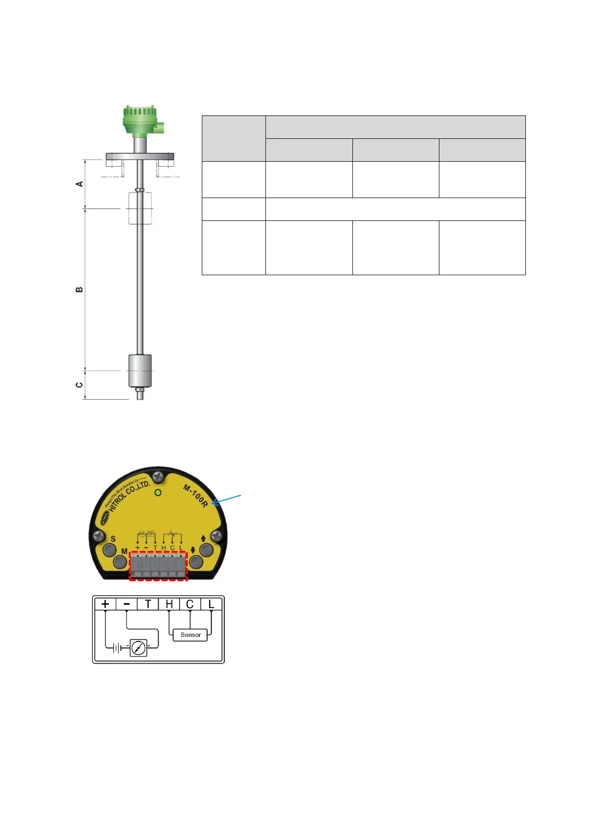
A = Upper Dead Band; Minimum length which cannot be measured from the
bottom of flange
B = Measuring Range; It can be different according to the material.
C = Lower Dead Band; Minimum length which cannot be measured from the
end of guide pipe.
(*) = If the measuring length is below than 600mm, the accuracy can be lower
than described.
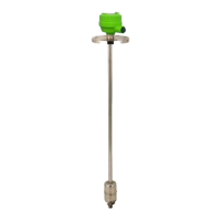
■ + -: DC 24V(DC 4~20mA Loop)
■ T: Output Test Point
■ H, C, L: Terminals between Sensor and M-100R
* Cable Color: H – Red, C – White, L – Black
■ Make sure to connect the power with correct polarity (+, −).
■ The power supply must be between +17 and +40V.
■ Do not connect the wire with the power connected.