ConTour Array™ 1.4
Table of Contents
A Notes on Rigging Safety. . . . . . . . . . . . . . . . . . . . . . . . . . . . . . . . . . . . . . . . . . . . . . . 5
1 Use . . . . . . . . . . . . . . . . . . . . . . . . . . . . . . . . . . . . . . . . . . . . . . . . . . . . . . . . . . . . . . . . . . . . . . . . . . . . . . 5
1.1 Intended Use . . . . . . . . . . . . . . . . . . . . . . . . . . . . . . . . . . . . . . . . . . . . . . . . . . . . . . . . . . . . . . . . . . . . . . 5
1.2 Unintended Use . . . . . . . . . . . . . . . . . . . . . . . . . . . . . . . . . . . . . . . . . . . . . . . . . . . . . . . . . . . . . . . . . . . . 5
2 Warranty and Liability. . . . . . . . . . . . . . . . . . . . . . . . . . . . . . . . . . . . . . . . . . . . . . . . . . . . . . . . . . . . . . . . 5
3 Notes on Safety for the HK AUDIO ConTour Array™ . . . . . . . . . . . . . . . . . . . . . . . . . . . . . . . . . . . . . . . 6
3.1 Responsibilities of the Operator . . . . . . . . . . . . . . . . . . . . . . . . . . . . . . . . . . . . . . . . . . . . . . . . . . . . . . . 6
3.2 Maintenance, Inspection and Repair of ConTour Array™ Rigging Hardware. . . . . . . . . . . . . . . . . . . . . 6
3.3 Technical Specifications of ConTour Array™ Rigging Hardware . . . . . . . . . . . . . . . . . . . . . . . . . . . . . . . 6
3.4 Maximum Number of Flown ConTour Array™ Enclosures . . . . . . . . . . . . . . . . . . . . . . . . . . . . . . . . . . . 6
3.5 Pick-points for Flying ConTour Array™ Enclosures . . . . . . . . . . . . . . . . . . . . . . . . . . . . . . . . . . . . . . . . . 6
3.6 Structural Modifications of ConTour Array™ Rigging Hardware . . . . . . . . . . . . . . . . . . . . . . . . . . . . . . 6
3.7 Original HK AUDIO Accessories . . . . . . . . . . . . . . . . . . . . . . . . . . . . . . . . . . . . . . . . . . . . . . . . . . . . . . . 6
3.8 Initiation and Operation . . . . . . . . . . . . . . . . . . . . . . . . . . . . . . . . . . . . . . . . . . . . . . . . . . . . . . . . . . . . . 6
B ConTour Array™ Speakers. . . . . . . . . . . . . . . . . . . . . . . . . . . . . . . . . . . . . . . . . . . . . . 8
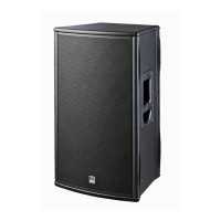
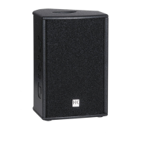
1 The CTA 208 Mid/High Unit . . . . . . . . . . . . . . . . . . . . . . . . . . . . . . . . . . . . . . . . . . . . . . . . . . . . . . . . . . 8
1.1 Specifications, CTA 208 . . . . . . . . . . . . . . . . . . . . . . . . . . . . . . . . . . . . . . . . . . . . . . . . . . . . . . . . . . . . . . 8
1.2 The CTA 208 Enclosures‘ Technical Data . . . . . . . . . . . . . . . . . . . . . . . . . . . . . . . . . . . . . . . . . . . . . . . . 9
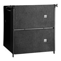
2 CTA 118 Sub . . . . . . . . . . . . . . . . . . . . . . . . . . . . . . . . . . . . . . . . . . . . . . . . . . . . . . . . . . . . . . . . . . . . . . 10
2.1 Specifications, CTA 118 Sub. . . . . . . . . . . . . . . . . . . . . . . . . . . . . . . . . . . . . . . . . . . . . . . . . . . . . . . . . . 10
2.2 Technical Data, CTA 118 Sub . . . . . . . . . . . . . . . . . . . . . . . . . . . . . . . . . . . . . . . . . . . . . . . . . . . . . . . . . .11
C Rigging ConTour Array™ Enclosures . . . . . . . . . . . . . . . . . . . . . . . . . . . . . . . . . . 12
1 Components and Applications of ConTour Array™ Rigging Hardware . . . . . . . . . . . . . . . . . . . . . . . . 12
1.1 Mounting the Rigging Frame. . . . . . . . . . . . . . . . . . . . . . . . . . . . . . . . . . . . . . . . . . . . . . . . . . . . . . . . . 12
1.2 Setting the DualCurve™ Angle . . . . . . . . . . . . . . . . . . . . . . . . . . . . . . . . . . . . . . . . . . . . . . . . . . . . . . . 12
1.3 Rigging Additional CTA 208 Mid/High Enclosures . . . . . . . . . . . . . . . . . . . . . . . . . . . . . . . . . . . . . . . 12
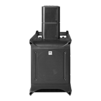
2 Ground stacking. . . . . . . . . . . . . . . . . . . . . . . . . . . . . . . . . . . . . . . . . . . . . . . . . . . . . . . . . . . . . . . . . . . 14
3 Mains and Generator Power Supply . . . . . . . . . . . . . . . . . . . . . . . . . . . . . . . . . . . . . . . . . . . . . . . . . . . 14
D The ConTour Array™ DDO-Pro™ Controller . . . . . . . . . . . . . . . . . . . . . . . . . . . 15
1 The DDO-Pro™ Net Port. . . . . . . . . . . . . . . . . . . . . . . . . . . . . . . . . . . . . . . . . . . . . . . . . . . . . . . . . . . . .15
2 Audio Signal Routing. . . . . . . . . . . . . . . . . . . . . . . . . . . . . . . . . . . . . . . . . . . . . . . . . . . . . . . . . . . . . . . .15
3 Handling the DDO-Pro™ Controller. . . . . . . . . . . . . . . . . . . . . . . . . . . . . . . . . . . . . . . . . . . . . . . . . . . .15
3.1 Level . . . . . . . . . . . . . . . . . . . . . . . . . . . . . . . . . . . . . . . . . . . . . . . . . . . . . . . . . . . . . . . . . . . . . . . . . . . . .15
3.2 Key Lock . . . . . . . . . . . . . . . . . . . . . . . . . . . . . . . . . . . . . . . . . . . . . . . . . . . . . . . . . . . . . . . . . . . . . . . . . .15
3.3 Utilities. . . . . . . . . . . . . . . . . . . . . . . . . . . . . . . . . . . . . . . . . . . . . . . . . . . . . . . . . . . . . . . . . . . . . . . . . . .15
3.4 Sub Delay . . . . . . . . . . . . . . . . . . . . . . . . . . . . . . . . . . . . . . . . . . . . . . . . . . . . . . . . . . . . . . . . . . . . . . . . 16
3.5 Delay. . . . . . . . . . . . . . . . . . . . . . . . . . . . . . . . . . . . . . . . . . . . . . . . . . . . . . . . . . . . . . . . . . . . . . . . . . . . 16
3.6 Sub Level . . . . . . . . . . . . . . . . . . . . . . . . . . . . . . . . . . . . . . . . . . . . . . . . . . . . . . . . . . . . . . . . . . . . . . . . 16
3.7 System Setup . . . . . . . . . . . . . . . . . . . . . . . . . . . . . . . . . . . . . . . . . . . . . . . . . . . . . . . . . . . . . . . . . . . . . 16
3.8 Quick Guide to the V1.01 Controller‘s Menu Structure . . . . . . . . . . . . . . . . . . . . . . . . . . . . . . . . . . . . 17
4 Technical Specifications, DDO-Pro™ Controller: . . . . . . . . . . . . . . . . . . . . . . . . . . . . . . . . . . . . . . . . . 18
E Service . . . . . . . . . . . . . . . . . . . . . . . . . . . . . . . . . . . . . . . . . . . . . . . . . . . . . . . . . . . . . . 19
1 Maintenance . . . . . . . . . . . . . . . . . . . . . . . . . . . . . . . . . . . . . . . . . . . . . . . . . . . . . . . . . . . . . . . . . . . . . 19
2 ConTour Array™ Spare Parts . . . . . . . . . . . . . . . . . . . . . . . . . . . . . . . . . . . . . . . . . . . . . . . . . . . . . . . . . 19
3 Replacing Loudspeakers and Voice Coils . . . . . . . . . . . . . . . . . . . . . . . . . . . . . . . . . . . . . . . . . . . . . . . 19
3.1 1", 8" and 18" Speakers . . . . . . . . . . . . . . . . . . . . . . . . . . . . . . . . . . . . . . . . . . . . . . . . . . . . . . . . . . . . . 19
3.2 The Drivers‘ Voice Coils. . . . . . . . . . . . . . . . . . . . . . . . . . . . . . . . . . . . . . . . . . . . . . . . . . . . . . . . . . . . . 19
4 Checking Speakers‘ Phase . . . . . . . . . . . . . . . . . . . . . . . . . . . . . . . . . . . . . . . . . . . . . . . . . . . . . . . . . . . 19
Table of Figures
Figure 1: CTA 208 ........................................................................................................8
Figure 2: CTA 208 housing dimensions [in mm]........................................................ 9
Figure 3: CTA 118 Sub .................................................................................................. 10
Figure 4: CTA 118 Sub housing dimensions [in mm] .................................................11
Figure 5: Integrated rigging attachments .................................................................12
Figure 6: ConTour Array™ rigging frame ..................................................................12
Figure 7: Shackles for attaching motors, chain hoists .............................................12
Figure 8: Mounting the rigging frame ....................................................................... 13
Figure 9: Setting an intermediate angle ................................................................... 13
Figure 10: Hoisting the mounted CTA 208 enclosure............................................... 13
Figure 11 a,b,c,d,e: Rigging additional CTA 208 enclosures .................................... 13
Figure 12 a, b: ConTour Array™ ground stack connectors ....................................... 14
Figure 13: ConTour Array™ stack plate ..................................................................... 14
Figure 14 a,b: Attaching the stack plate to the CTA 118 Sub................................... 14
Figure 15 a,b,c: CTA 208 Mid/High stack.................................................................. 14
Figure 16: DDO-Pro™ network .................................................................................. 15
Figure 17: DDO-Pro™ Controller panel ..................................................................... 15
Figure 18 a,b,c,d,e,f: System Setups ......................................................................... 16
Figure 19: Menu structure of the DDO-Pro™ Controller ........................................17