ital outputs to these three-pin
pin
3 = signal. The FIRNET controller accepts sampling rates of
8 kHz and 96 kHz, which ma
be selected via a menu option.
nput-Output Signal Routing
The analog INPUT A – that is, the left channel of the digital AES/EBU
signal - delivers the signal to OUTPUT A and OUTPUT B. OUTPUT C and
UTPUT D receive their signal from analog INPUT B, that is, the right
channel o
the digital AES/EBU signal. You can reroute signals in the
18 AES/EBU OUT Digital Audio Output
The signal patched into the AES/EBU input can be routed through in
digital format to other devices via this three-pin male XLR port. Pin
ssignments are pin 1 = groun
es the incoming digital audio signal to preserve signal quality. I
IRNET controller drops out, the si
nal is routed directly from the di
ital AES/EBU OUT via a parallel circuit.
To select the di
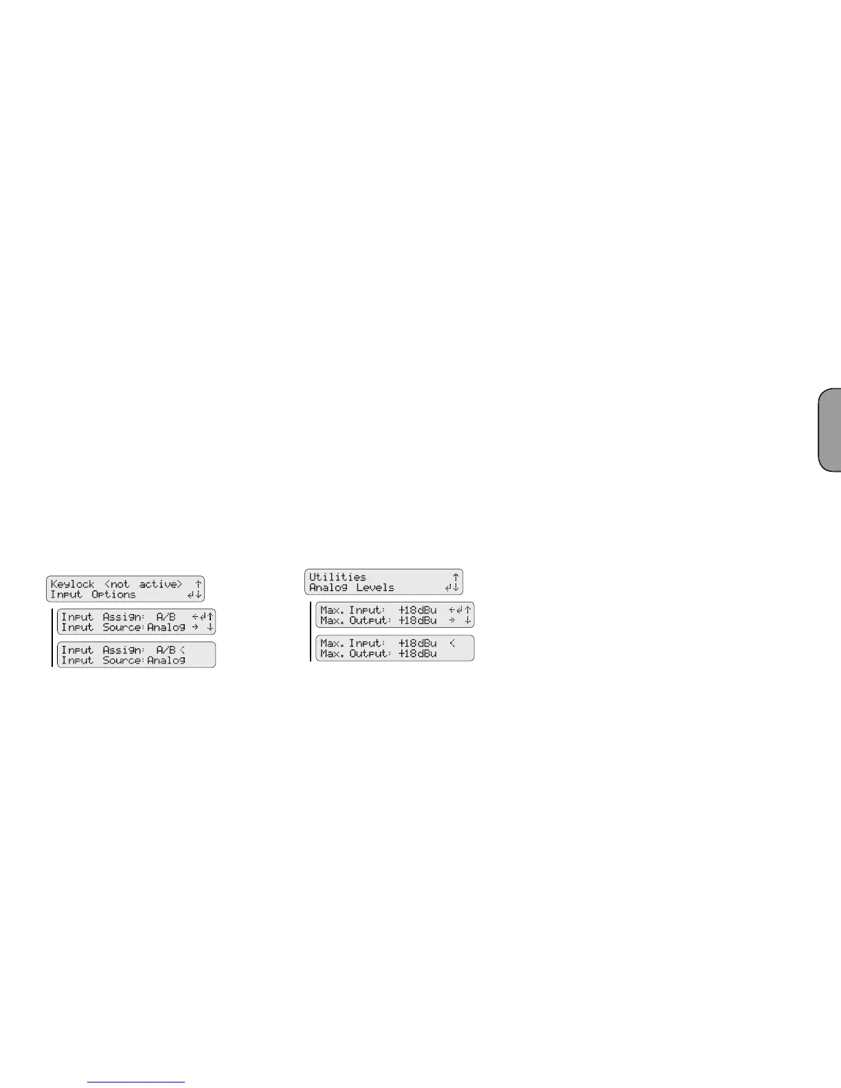
o to the Admin menu (press ADMIN once),
choose the menu option Input Options (press 1x
S
), and then press
DMIN/Input Options/ Input Source
f you wish to address several FIRNET controllers via their analog inputs,
AES/EBU OUT outputs
to synchronize these controllers to ensure the audio signal remains
rst FIRNET controller’s digital AES/EBU OUT
to t
rst FIRNET’s digital AES/EBU IN and the last FIRNET’s digi
tal AES/EBU OUT unoccupied. The
rst FIRNET is the master, providing
he clock for the other slaved controllers, so access this FIRNET’s menu
unction to select the internal clock. Con
ure the other controllers so
select their analog inputs for the audio signal using the appropriate
menu o
Note: The Sync LED on subsequent controllers in the network light up to
confirm they are synchronized.
19 INPUT A, INPUT B Analog Audio Input
onnect signal sources with analog outputs to these three-pin
ets. Pin assignments are pin 1 = groun
k-ohms. An electronic fi lter protects them against HF interference
menu option lets you adjust input sensitivity in four steps
(6
o to the Admin menu (press ADMIN once), choose the
menu option Analog Levels (press down arrow thrice), and then confi rm
Menu option - ADMIN/Analog Level
The FIRNET uses stacked AD converters to achieve >128 dB (A) input
dynamic range.
Note: You must manually set analog levels to
18 dBu after a firmware update.
20 OUTPUT A to OUTPUT D Analo
ets to route output signa
s to power
amps. Pin assignments are pin 1 = groun
pin 3
= signal (-). These electronically balanced connectors’ output impedance
menu option lets you adjust the maximum output level in
our steps
(6 dBu, 12 dBu, 18 dBu, 24 dBu) to match the levels of the FIRNET
controller’s output and the connected power amp’s analo
Note: Adjust the following settings to ensure the FIRNET operates
properly with the given power amps:
When using FP10000Q amps:
Gain LAB: + 26 dBu
Max D/A Level FIRNET (Admin view): + 18 dBu
When using VX 2400 amps:
Gain VX: + 35 dBu
Max A/D level FIRNET (Admin view): +6 dBu
English
 Loading...