e next or previous menu option
• Selects and changes parameters in the edit windows
• Top key: Arrow up while scrolling in the menu
• Bottom key: Arrow down while scrolling in the menus
• Right key to the right to adjust (lower numerical values
t key to adjust parameter values (lower numerical values
rm the adjusted value
13 Reset Button
The FIRNET controller reboots after 10 seconds
t Reset and Hard Reset key combinations
Th
no fi lter selected
• No signa
parameter set to 0
• IIR EQs a
input gains set to 0,
• IIR EQs output set to bypass (LIPAN O
• All limiters set to + 1
• Admin parameters remain unchan
Speaker+Admin+Back for 3 seconds
Max. output + 6 dBu (setting
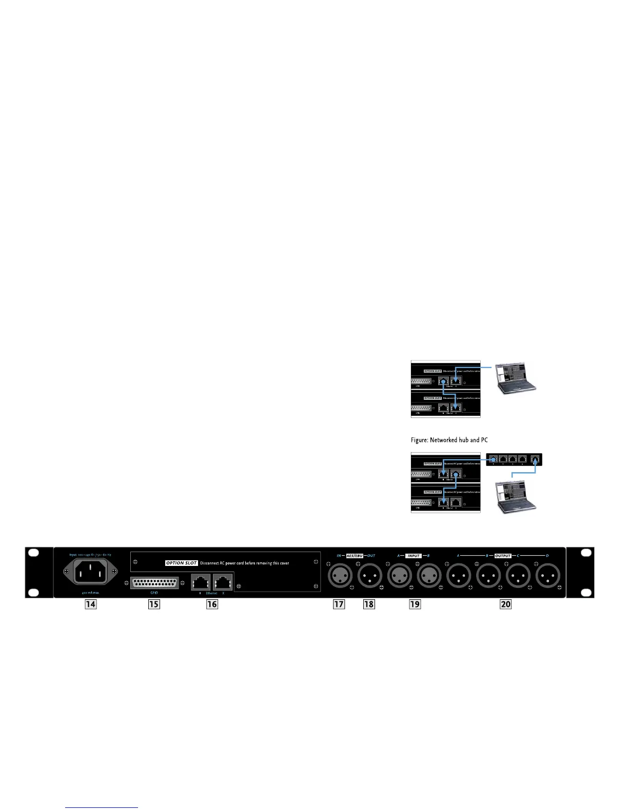
4 100-240 V~ / 50-60 Hz Mains
his three-pole non-heating equipment connector with a ground contact
e power supply unit allows the controller to be connected directly
ransformers and the like. Its maximum power consumption is 40 VA,
hich corresponds to about 175 mA maximum current consumption at
30 V mains voltage and about 400 mA at 100 V. Do not connect the
evice using anything other than a three-pole connector with a ground
ontact. The mains outlet must also be equipped with a
ever use damaged cords, plugs, or sockets
his 25-pin sub-D port provides four each fl oating inputs and outputs
or future fi rmware versions’ use, for example, to remote-control power
amps or switch controlled devices. Current
Ethernet PC Control Ports
Ethernet ports relay remote control and monitorin
data between a PC
and FIRNET controllers via computer networking hardware. The Ethernet
and Ethernet II connectors are RJ-45 ports
Input X = for cross input,
II = parallel input).
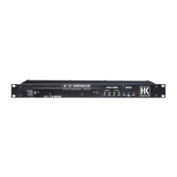
Ca
urther network hardware such as hubs and
switches, connect the PC’s network port to the
rst FIRNET’s Ethernet
X port using CAT5 networ
rst FIRNET’s Ethernet II port to the second controller’s
Ethernet X port, and so
orth.
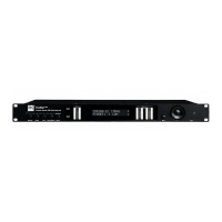
Use a CAT5 network cable to connect the FIRNET controller to hubs or
switches, patching the FIRNET controller’s Ethernet II port to the hub
or switch’s network port. To daisy-chain further FIRNET controllers,
connect the
rst FIRNET’s Ethernet X port to the second controller’s
Ethernet II port, and so
ou connect all FIRNET controllers to switches.
If you do not, and one controller fails in setups comprising several
connecte
 Loading...