isplay
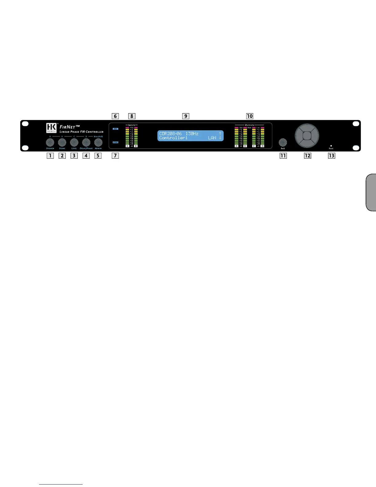
The LCD shows information on
arameters. The default
readout appears a
ter the device is powered up, and then the displa
nce you begin navigating adjustable parameters, it shows values
pertaining to t
ccess the various parameter sections. You can adjust the indicated para
back key) for the selected input and output. Pressing the back key always
ta
.
Note: The device retains stored values even if a power failure occurs or it
is unplugged from the mains supply.
FirNet
ortcuts to Mute Outputs A/B/C/
ou can use combinations of the Admin menu key and the four other
menu
e FIRNET’s
output channels in A/B/C/D sequence. For example, if you wish to mute
output A, press Admin + Speaker; to mute output D, press Admin +
elay/Phase. Press the same combination a
ain to reactivate the output.
Note: Each of the output channels’ red signal LEDs show the given
output’s mute status (constant red = MUTE).
• Selects a speaker-speci
rom the FIRNET speaker series
• Loads scenes setups from the FIRNET database and stores them
to t
usts input and output levels in the range o
-40 dB to 12 dB
• Increment = 0.1 dB in the range of 12 dB to -12 d
usts delay time up to 500 ms for the FIRNET controller’s inputs
• Ad
usts delay time up to 25 ms for the FIRNET controller’s output
• Inverts the phase position of the audio signal routed to the FIRNET
controller’s inputs and output
ey
• Locks keys to prevent unauthorized or unintentional handlin
options
• Adjusts peak analog input and output levels to match FIRNET to
upstream or downstream audio devices
• E
ay contrast
• Serves to select the delay unit o
t, samples) and
enter the surroundin
temperature to calculate the speed of sound
6 AES IN LED Displa
or the FIRNET’s synchronization option and the device receives an
incoming signa
• Green segment: Audio input level in the range of -48 to -12 dB
at
• Yellow segment: Audio input level in the range of -12 to 0 dB
e AD converter
Note: An overdriven AD converter generates distortion that the FIRNET’s
limiter cannot suppress. If the red LED lights up, set the FIRNET’s
input gain to a higher value (see the section Setting Peak AD Level in
the Adjusting Parameters chapter) or reduce the source audio device’s
output level! Be sure to heed the gain level recommendations for
connected amps, particularly when operating an FP10000Q power amp.
fi lter, and the existence of a network lin
en you access a menu
10 OUTPUT LED Displays
10 LEDs, green/yellow/red
• Green segment: Audio input level in the range of -48 to -12 dB below
the limiter v
lue
• Yellow segment: Audio input level in the range o
ue
• Red segment: Limiter is attenuating the audio input level. The given
output is mute
 Loading...