Copyright HK Instruments 2018 www.hkinstruments. Installaon version 6.0 2018
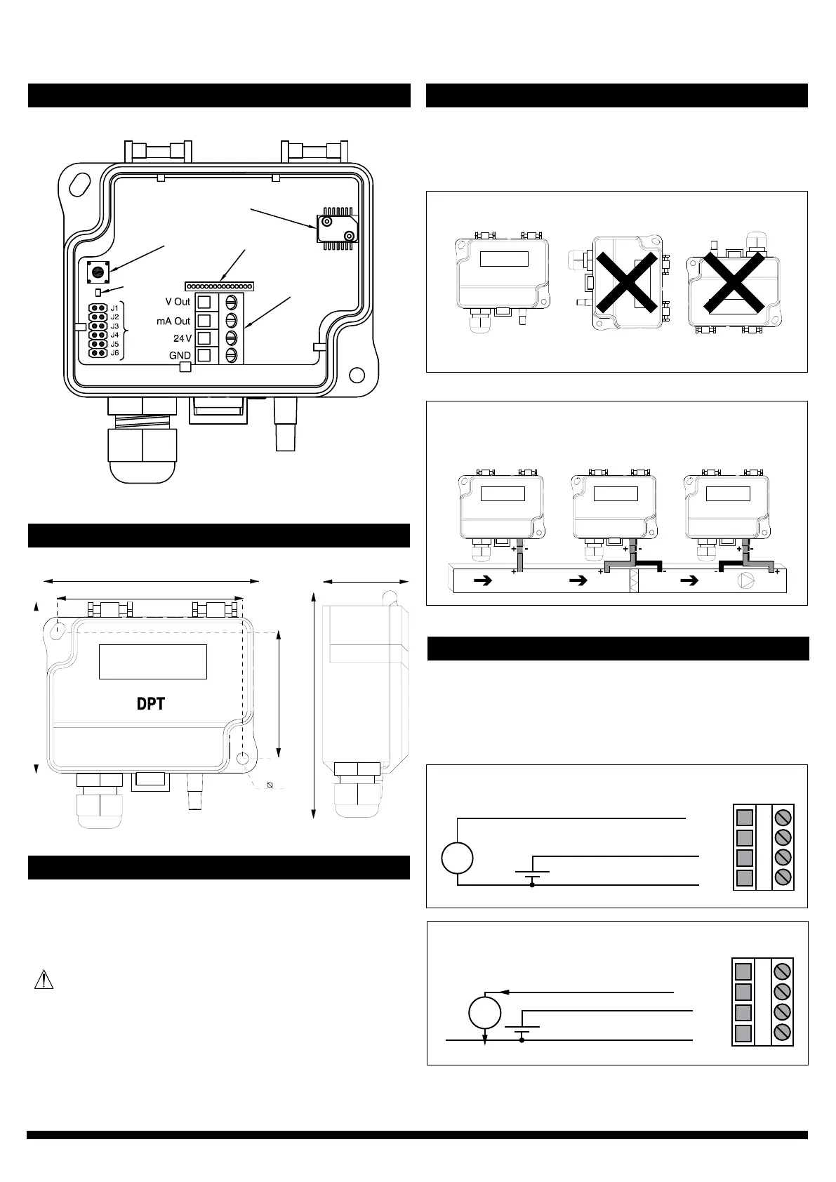
SCHEMATICS
DIMENSIONAL DRAWINGS
INSTALLATION
STEP 1: MOUNTING THE DEVICE
1)Mountthedeviceinthedesiredlocaon(seestep1).
2)Openthelidandroutethecablethroughthestrainreliefand
connectthewirestotheterminalblock(s)(seestep2).
3)Thedeviceisnowreadyforconguraon.
WARNING!Applypoweronlyaerthedeviceisproperlywired.
Figure 1a - Mounng orientaon
Figure 1b - Applicaon connecons
1)Selectthemounnglocaon(duct,wall,panel).
2)Usethedeviceasatemplateandmarkthescrewholes.
3)Mountwithappropriatescrews.
Pressure sensor
Zero buon
Connecon for
oponal display
Terminal block
LED
Jumpers
YES NO NO
Stac pressure Filter/Damper
monitoring
Fan/Blower
monitoring
Not
connected
77.0
71.5
53.0
4.3
95.0
36.0
STEP 2: WIRING DIAGRAMS
ForCEcompliance,aproperlygroundedshieldingcableisrequired.
1)Unscrewthestrainreliefandroutethecable(s).
2)Connectthewiresasshowningure2aand2b.
3)Tightenthestrainrelief.
Figure 2a - Wiring diagram 0–10 V output
Figure 2b - Wiring diagram 4–20 mA output
V
0–10 V
4–20 mA
24 V
GND
+ Power supply
24 VDC / 24 VAC
A
0–10 V
4–20 mA
24 V
GND
+ Power supply
24 VDC / 24 VAC